A DC motor energy consumption braking control system

A technology of energy-consumption braking and control system, which is applied in the direction of DC motor deceleration device, electric motor/converter plug, etc., and can solve the problems of high energy loss, difficult popularization and application, and difficult guarantee of system stability and reliability. , to achieve the effect of simple system structure and convenient maintenance

Active Publication Date: 2017-07-04
四川中曼电气工程技术有限公司
View PDF5 Cites 0 Cited by
  • Summary
  • Abstract
  • Description
  • Claims
  • Application Information

AI Technical Summary

Problems solved by technology

But the effect of doing so is not very ideal, and there are the following problems:
[0005] (1) The connected thyristor rectifier must always have current output, and the energy consumption braking resistor is always in the heating device, and the energy loss is very high; (2) The current output by the thyristor rectifier needs to change constantly and quickly Responsive, but it is very difficult to achieve both precision and high real-time performance in control; (3) The dynamic adjustment of the system depends not only on the equipment itself in each link of the system, but also on the DC series excitation motor. It is related to the calculation method of dynamic braking, so it is very difficult to accurately control the speed during the entire dynamic braking process; (4) The performance of the thyristor rectifier has a great influence on the normal use of the entire system Therefore, it is difficult to guarantee the stability and reliability of the entire system, and it is also difficult to obtain a wide range of promotion and application

Method used


Image

  • A DC motor energy consumption braking control system

Examples


Embodiment Construction

[0013] The technical solution of the present invention will be further described in detail below in conjunction with the accompanying drawings, but the protection scope of the present invention is not limited to the following description.

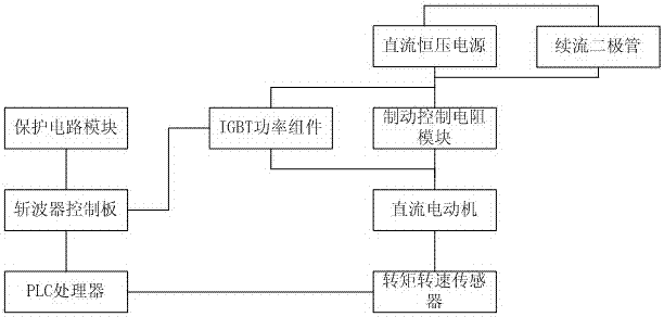
[0014] Such as figure 1 As shown, a DC motor dynamic braking control system includes a DC motor, a DC constant voltage power supply that provides voltage for the DC motor, a torque speed sensor, a PLC processor, a chopper control board, an IGBT power component and a control panel. Dynamic control resistor module, the voltage output of the DC constant voltage power supply is connected to the voltage input of the DC motor through the brake control resistor module, the DC motor is connected to the torque speed sensor, the output of the torque speed sensor is connected to the input of the PLC processor, and the PLC The output of the processor is connected to the input of the chopper control board, the output of the chopper control board is conn...


PUM


Abstract

The invention discloses a dynamic braking control system of a direct current motor, which comprises direct current motor, a direct current constant voltage source, a torque and rotating speed sensor, a PLC (programmable logic controller) processor, a chopper control board, an IGBT (insulated gate bipolar transistor) power component and a braking control resistance module, wherein a voltage output of the direct current constant voltage source is connected with a voltage input of the direct current motor via the braking control resistance module; the direct current motor is connected with the torque and rotating speed sensor; an output of the torque and rotating speed sensor is connected with an input of the PLC processor; an output of the PLC processor is connected with an input of the chopper control board; an output of the chopper control board is connected with an input of the IGBT power component; and the IGBT power component is in parallel connection with the braking control resistance module. According to the system, the braking control resistance module is cut off by the PLC processor under different conditions, so that rotating speed and torque outputs of the direct current motor change to achieve dynamic braking.

Description

technical field [0001] The invention relates to a DC motor energy consumption braking control system. Background technique [0002] DC series motor, that is, a DC motor in which the armature is connected in series with the field coil. This kind of motor is generally driven by a three-phase 6-pulse thyristor rectifier device. The rectifier adjusts the DC output voltage to change the motor speed; adjusts the DC output current to change the motor torque. However, this kind of motor can only do single-quadrant operation (that is, the speed and torque are in the same direction) in most occasions, and the energy consumption braking in the general sense is to cut off the power of the motor to stop the rising process of the load. But it cannot prevent the load from falling under the action of gravity thereafter. In practice, it is necessary to use auxiliary brakes based on mechanical friction or electromagnetic principles to control the load to move downward or stop at a certain ...

Claims


Application Information

Patent Timeline
Patent Type & Authority Patents(China)
IPC IPC(8): H02P3/12
Inventor 赵军民陈克利刘育生周翼
Owner 四川中曼电气工程技术有限公司
Why Eureka
Try Eureka