Supercharge Your Innovation With Domain-Expert AI Agents!

Tandem rotation detector

a detector and tandem technology, applied in the direction of steering linkages, instruments, transportation and packaging, etc., can solve the problems of conventional tandem detectors, however, and achieve the effects of reducing the influence of leakage flux between the rotation angle detection mechanism, ensuring high-precision detection, and ensuring continuous detection

Inactive Publication Date: 2005-04-21
MINEBEA CO LTD
View PDF3 Cites 1 Cited by
  • Summary
  • Abstract
  • Description
  • Claims
  • Application Information

AI Technical Summary

Benefits of technology

[0012] The present invention has been made in view of the above problems, and it is an object thereof to provide a tandem rotation detector capable of reducing the influence of leakage flux between rotation angle detection mechanisms so that high-precision detection can be always done even under normal magnetic field environments.
[0017] The tandem rotation detector of the present invention includes the first rotation detection mechanism configured to generate a magnetic flux through the coil of the first outer core provided inside the cylindrical housing for detecting the rotation angle of the rotary shaft arranged in the central portion of the housing, and the second rotation detection mechanism which is placed side by side with the first rotation detection mechanism and configured to generate a magnetic flux through the coil of the second outer core provided inside the housing for detecting the rotation angle of the rotary shaft. With this structure, since the housing is formed from a nonmagnetic material, the influence of leakage flux between the rotation angle detection mechanisms can be reduced, and hence high-precision detection can be always realized.
[0018] If the shielding plate is provided between the first rotation detection mechanism and the second rotation detection mechanism, the influence of the leakage flux between the rotation angle detection mechanisms can be further reduced.
[0019] Further, if the rotary shaft comprises two rotary shafts arranged in series, the first rotation detection mechanism and the second rotation detection mechanism can detect the rotation angles of the two rotary shafts respectively, thereby enabling high-precision detection of the two rotary shafts at all times.
[0020] On the other hand, if the rotary shaft comprises a single continuous rotary shaft, the first rotation detection mechanism and the second rotation detection mechanism can detect a rotation angle difference to detect the rotational torque of the rotary shaft, thereby enabling high-precision detection of the rotational torque at all times.

Problems solved by technology

The conventional tandem rotation detector, however, has the following problems.

Method used


Image

  • Tandem rotation detector
  • Tandem rotation detector
  • Tandem rotation detector

Examples


Embodiment Construction

[0025] A tandem rotation detector according to an embodiment of the present invention will now be described with reference to the accompanying drawings.

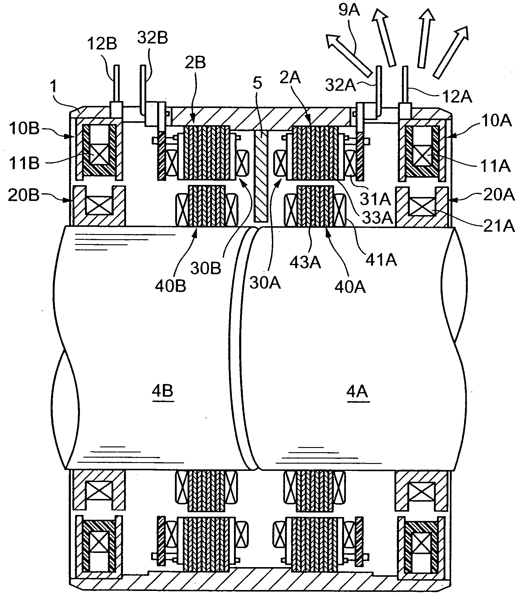
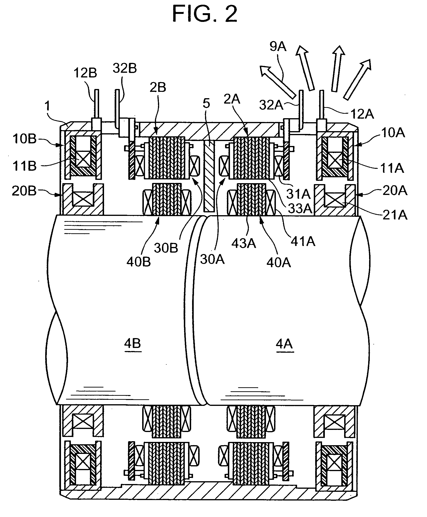
[0026]FIG. 2 is a sectional side view of a tandem rotation detector according to the embodiment of the present invention.

[0027] As shown in FIG. 2, a rotation detector according to the embodiment of the present invention has a rotary shaft 4A and a rotary shaft 4B arranged in series in a cylindrical housing 1. A first rotation angle detection mechanism 2A for detecting the rotation angle of the rotary shaft 4A, and a second rotation angle detection mechanism 2B for detecting the rotation angle of the rotary shaft 4B are provided inside the housing 1. In the first rotation angle detection mechanism 2A, a first outer core 10A and a first stator core 30A are arranged in parallel. A first inner core 20A is mounted on the rotary shaft 4A so as to face the first outer core 10A, and a first rotor core 40A is mounted on the rotary shaft 4A...


PUM


Abstract

A tandem rotation detector capable of reducing the influence of leakage flux between rotation angle detection mechanisms so that high-precision detection can be always done under normal magnetic field environments includes a first rotation detection mechanism 2A configured to generate a magnetic flux through a coil 11A of a first outer core 10A mounted inside a cylindrical housing 1 for detecting the rotation angle of a rotary shaft 4A arranged in the central portion of the housing 1, and a second rotation detection mechanism 2B, placed side by side with the first rotation detection mechanism 2A, configured to generate a magnetic flux through a coil 11B of a second outer core 10B mounted inside the housing 1 for detecting the rotation angle of a rotary shaft 4B arranged in the central portion of the housing in series with the rotary shaft 4A, in which the housing 1 is formed from a nonmagnetic material.

Description

BACKGROUND OF THE INVENTION [0001] 1. Field of the Invention [0002] The present invention relates to a tandem rotation detector capable of reducing the influence of leakage flux between rotation angle detection mechanisms so that high-precision detection can be always realized. [0003] 2. Description of the Prior Art [0004]FIG. 1 shows a sectional side view of a conventional tandem rotation detector. [0005] As shown in FIG. 1, this kind of tandem rotation detector (for example, see Japanese Patent Application Laid-Open No. 2003-098019) is used to detect the rotation angles of rotary shafts. The rotation detector has a rotary shaft 104A and a rotary shaft 104B arranged in series in a central portion of a cylindrical housing 101. A first rotation angle detection mechanism 102A for detecting the rotation angle of the rotary shaft 104A, and a second rotation angle detection mechanism 102B for detecting the rotation angle of the rotary shaft 104B are arranged inside the housing 101. In th...

Claims


Application Information

Patent Timeline
IPC IPC(8): B62D6/10G01B7/00G01B7/30G01L3/10G01L5/22
CPCB62D6/10G01L3/109G01L3/101G01L3/105
Inventor MATSUURA, MUTSUMI
Owner MINEBEA CO LTD
Features
  • R&D
  • Intellectual Property
  • Life Sciences
  • Materials
  • Tech Scout
  • Unparalleled Data Quality
  • Higher Quality Content
  • 60% Fewer Hallucinations
Learn More