

Remote electrical power monitoring systems and methods
- Summary
- Abstract
- Description
- Claims
- Application Information
AI Technical Summary
Problems solved by technology
Method used
Image

Examples
Embodiment Construction
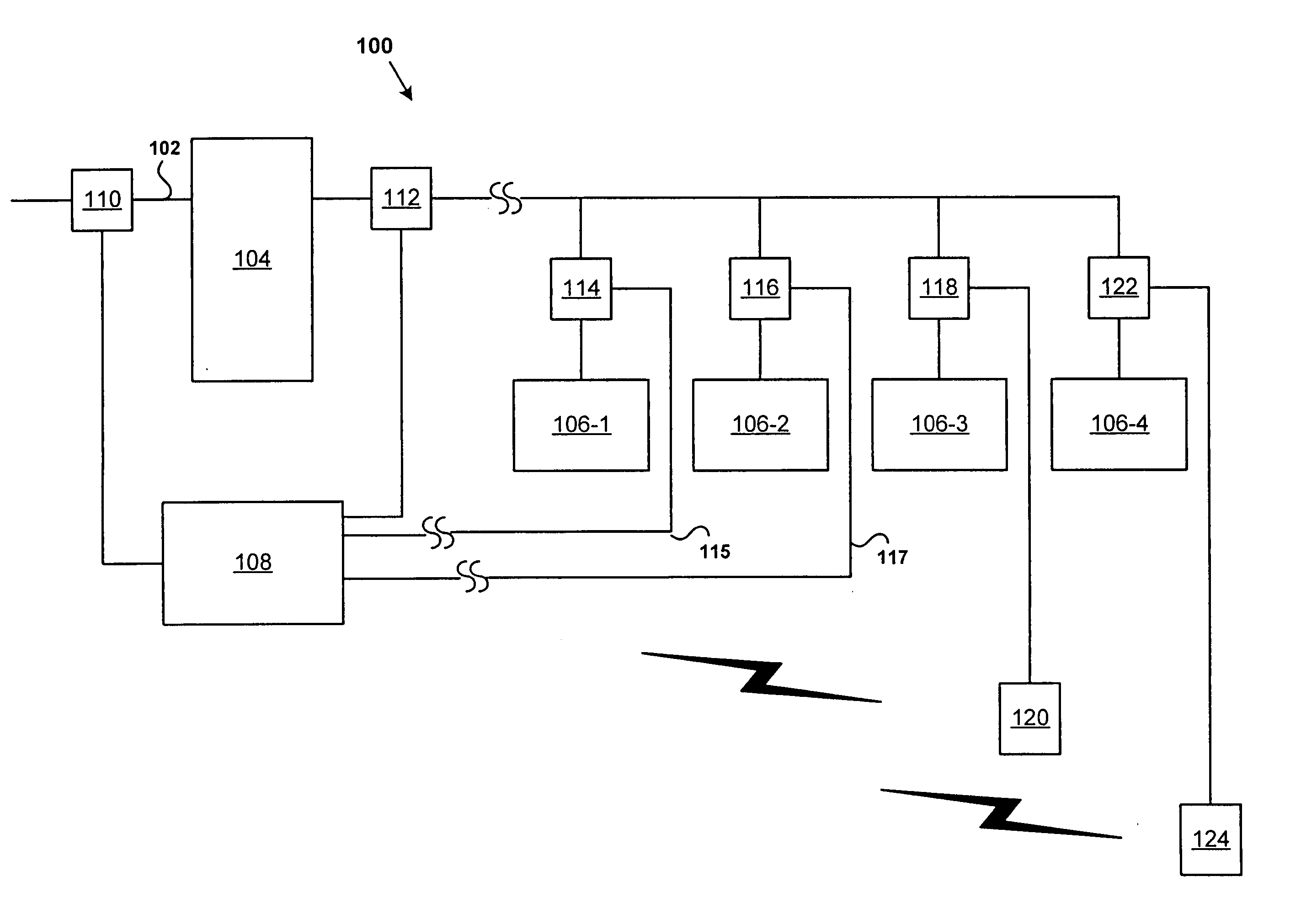
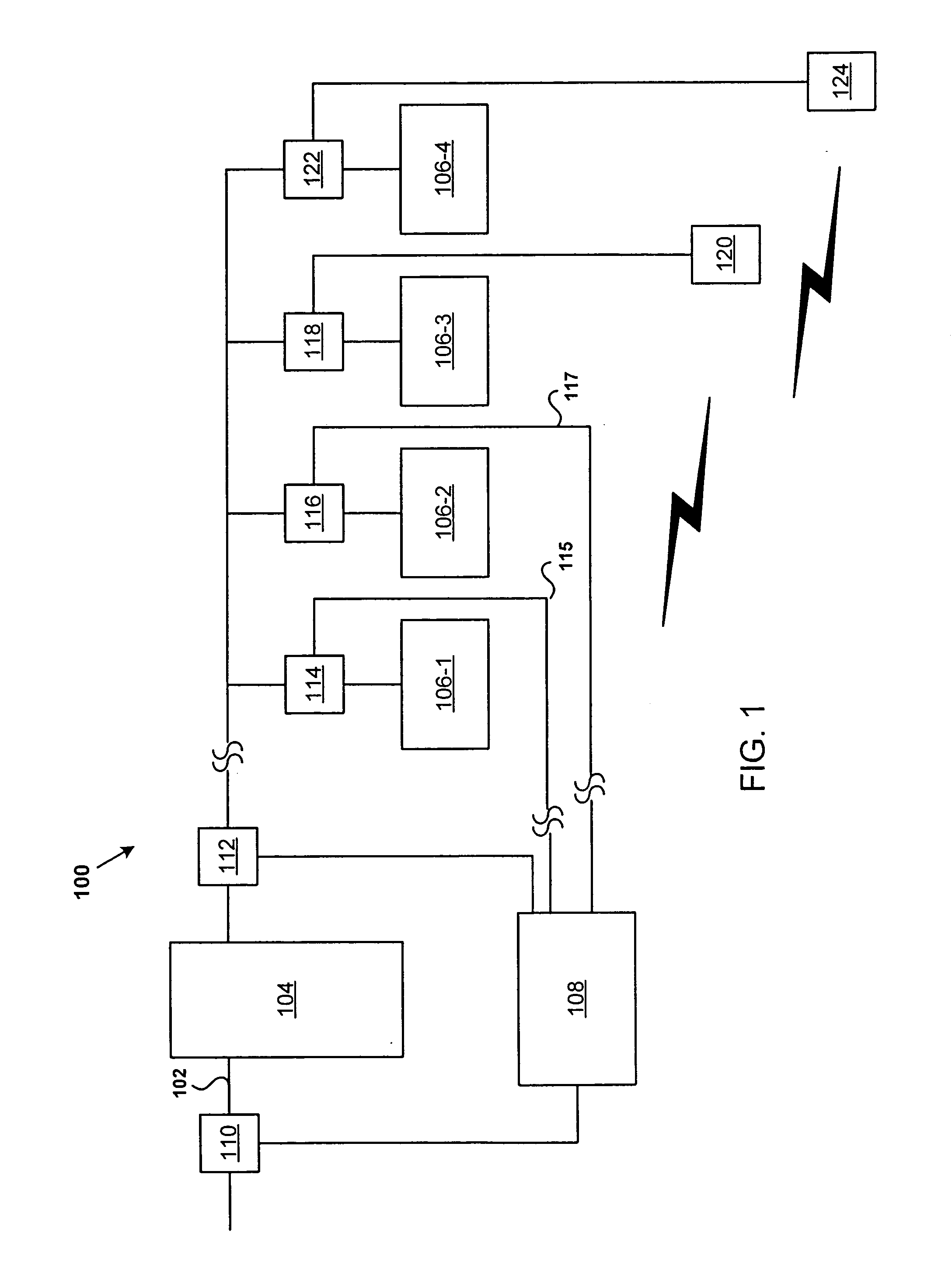
[0017] Embodiments of the invention relate to remote electrical power monitoring systems and methods. According to some embodiments, mean absolute voltage in an electrical distribution system is measured at a distribution panel, breaker, or other central location. A non-intrusive current sensor is attached to a distribution line feeding a load for which power monitoring is desired and is configured to measure the current magnitude and waveform characteristics. The load is located some distance from the central location. A non-intrusive voltage phase sensor (e.g., a capacitive tap) also is located at the remote load and measures the voltage waveform characteristics, with the exception of mean absolute voltage. The voltage waveform is combined with the current magnitude and waveform to produce a power component that need only be scaled using the mean absolute voltage measurement to produce the absolute power measurement that is desired. The un-scaled power component and the mean absol...
PUM
 Abstract
Description
Claims
Application Information