Fluid control valve and droplet discharging device

a technology of fluid control valve and droplet, which is applied in the direction of valve housing, mechanical equipment, coatings, etc., can solve the problems of foam discharge, droplet unstably discharged due to foam, and uneven discharging amount of cleaning liquid at the time of head cleaning operation, so as to reduce the likelihood, prevent the effect of foam in the fluid control valve from being retained or secured at the initial discharging quality of the droplet discharging head

Inactive Publication Date: 2005-04-21
SEIKO EPSON CORP
View PDF4 Cites 16 Cited by
  • Summary
  • Abstract
  • Description
  • Claims
  • Application Information

AI Technical Summary

Benefits of technology

[0011] Exemplary aspects of the present invention address or solve the above and / or other problems. Exemplary aspects of the present invention provide a fluid control valve which can reduce or prevent the foam from being retained inside the valve and further reduce or prevent the other fluid equipment placed downstream from causing defects due to the foam, and to provide a droplet discharging device using the fluid control valve.
[0019] According to this structure, because the outflow port is provided generally at the center part of the upper surface of the tank, the foam gathered at the upper surface of the tank easily gathers to the outflow port by fluid flow. For this reason, the foam easily flows out from the tank, and the foam is not retained in the tank.
[0027] By using the fluid control valve according to an exemplary aspect of the present invention, the droplet discharging device according to an exemplary aspect of the present invention can reduce the likelihood or prevent the foam retained in the fluid control valve from flowing into the droplet discharging head and the cleaning liquid supply part. For this reason, a lack of cleaning on the periphery part of the nozzle due to the liquid material discharging failure from the droplet discharging head and a cleaning liquid discharging failure from the cleaning liquid supply part can be reduced or prevented. As a result, loss of drawings due to the liquid material discharging failure and a flight curve of the liquid material, due to the lack of cleaning on the periphery part of the nozzle, can be reduced or prevented. Thereby the initial discharging quality of the droplet discharging head can be secured.
[0028] Furthermore, the foam in the fluid control valve can be reduced or prevented from being retained. Therefore, a process to remove the foam becomes unnecessary and maintenance time is reduced to enhance the productivity.

Problems solved by technology

There has been a problem that if foam flows downstream together with fluid, this may cause a failure in the other fluid equipment placed downstream of the fluid control valve.
When the foam intrudes into the droplet discharging head, the droplet is unstably discharged due to the foam.
Furthermore, when the foam, that is retained in the fluid control valve in a cleaning liquid supply system and has become large, blocks the flow passage, the discharging amount of the cleaning liquid at the time of a head cleaning operation becomes uneven, and sufficient cleaning is not carried out.
Also contaminants may remain on nozzle portions of the droplet discharging head.

Method used


Image

  • Fluid control valve and droplet discharging device
  • Fluid control valve and droplet discharging device
  • Fluid control valve and droplet discharging device

Examples


Embodiment Construction

[0035] An exemplary embodiment of the present invention will be described with reference to FIG. 1 through FIG. 6.

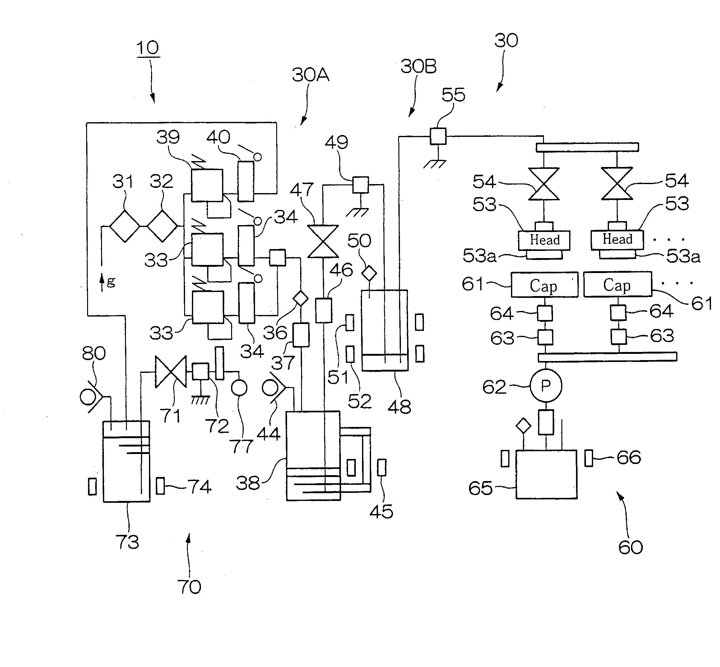
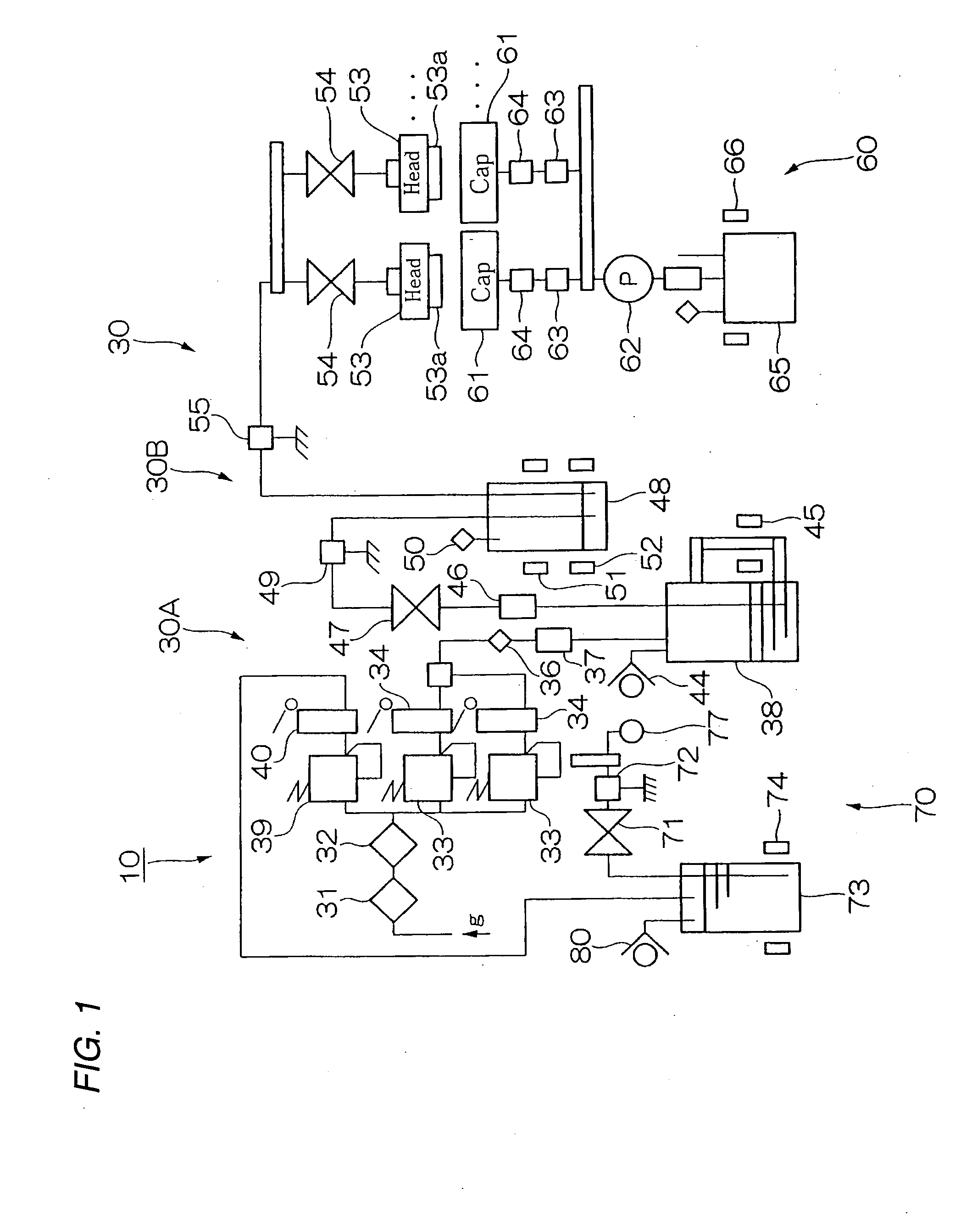
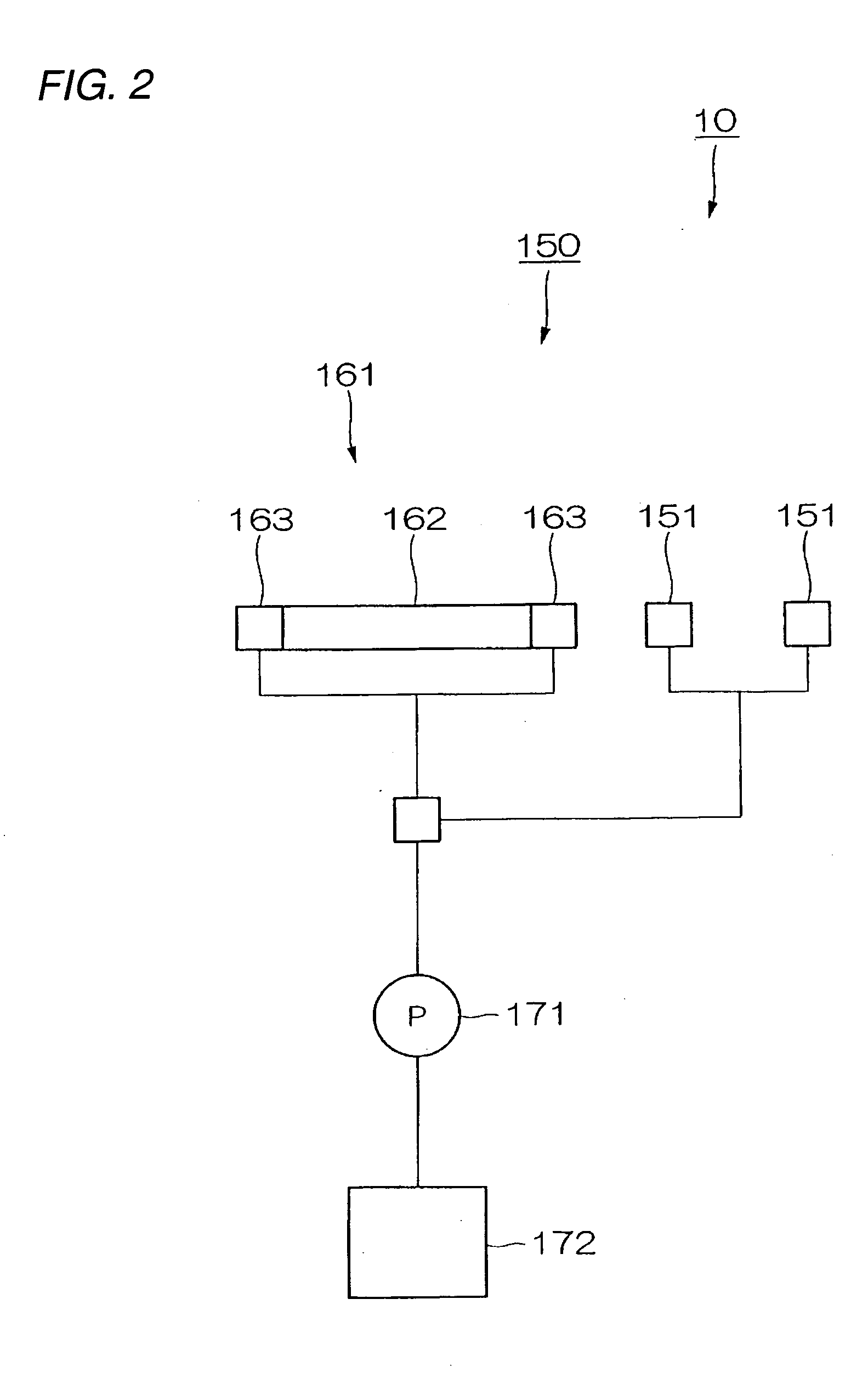
[0036]FIG. 1 is a schematic of a droplet discharging device according to the present exemplary embodiment. FIG. 2 is a schematic of a blank dot detecting and preventing unit of the droplet discharging device according to the present exemplary embodiment.

[0037] As shown in FIG. 1 and FIG. 2, a droplet discharging device 10 includes a droplet discharging unit 30, a cap unit 60, a wiping unit (cleaning device) 70, and a blank dot detecting and preventing unit 150.

[0038] The droplet discharging unit 30 is a unit to discharge and lay down an ink droplet R on a predetermined position on a substrate (glass substrate, hereinafter, wafer Wf) from a droplet discharging head 53.

[0039] As shown in FIG. 1, the droplet discharging unit 30 includes a pressurized system 30A to supply an inert gas at a predetermined pressure, an ink droplet supply system (first supply flow passage) 3...


PUM


Abstract

A fluid control valve capable of reducing or preventing a foam from being retained inside and reducing the likelihood or preventing the other fluid equipment placed downstream from causing a failure due to the foam, and a droplet discharging device using the fluid control valve, are provided. Fluid control valves and include a tank through which fluid flows, an inflow port through which fluid flows into the tank, an outflow port through which fluid flows out from the tank and a valve body for opening and closing the inflow port or the outflow port, the inflow port being provided below the outflow port.

Description

BACKGROUND OF THE INVENTION [0001] 1. Field of Invention [0002] Exemplary aspects of the present invention relate to a fluid control valve and a droplet discharging device. [0003] 2. Description of Related Art [0004] There are various types of related art fluid control valves that control flow of fluid. [0005] For example, a related art fluid control valve which on-off controls flow of fluid flowing through the value by using a valve seat formed in a flow passage and valve body which contacts or separates from the valve seat is disclosed in Japanese Unexamined Patent Publication No. 2002-310316. SUMMARY OF THE INVENTION [0006] As described above, in a related art fluid control valve, when fluid is initially filled into the fluid control valve, the inside of fluid control valve is not completely filled with fluid and a foam may remain inside. Further, if a plurality of foams are retained in the fluid control valve, a larger foam may be formed by the plurality of foams joining togethe...

Claims


Application Information

Patent Timeline
Patent Type & Authority Applications(United States)
IPC IPC(8): B41J2/175B05C5/00B05C11/10B41J2/165B41J2/19F16K27/00F16K27/02
CPCB41J2/175B41J2/19B41J2/17596B41J2/16517B41J2/16552
Inventor NAKAMURA, SHINICHI
Owner SEIKO EPSON CORP
Why Eureka
Try Eureka