Optical device and projector

a technology of optical modulator and projector, which is applied in the direction of picture reproducers using projection devices, non-linear optics, instruments, etc., can solve the problems of pixel deviation on the projection image, optical modulator displacement, etc., and achieve the effect of enhancing the rigidity

Inactive Publication Date: 2005-04-21
SEIKO EPSON CORP
View PDF6 Cites 0 Cited by
  • Summary
  • Abstract
  • Description
  • Claims
  • Application Information

AI Technical Summary

Benefits of technology

[0031] With this arrangement, since the projector includes the above-descried optical device, the same effects and advantages as the above-described optical device can be obtained.
[0032] Additionally, since the projector includes the optical device, the rigidity of which is enhanced, the projection optical device can constantly projects a vivid image.

Problems solved by technology

However, in the optical device described in Patent Document 1, since the optical modulator is supported and fixed by the plurality of pin spacers relative to the color-combining optical device, an external force against the optical device may cause each of the spacers to be inclined, and inclination of the pin spacer may further cause displacement of the optical modulator relative to the color-combining optical device.
Owing to this, the position of the plurality of optical modulators may mutually be displaced, thereby resulting in pixel deviation on a projection image.

Method used


Image

  • Optical device and projector
  • Optical device and projector
  • Optical device and projector

Examples


first embodiment

1. FIRST EMBODIMENT

[0042] A first embodiment of the present invention will be described below with reference to the attached drawings.

[1-1 Configuration of Projector]

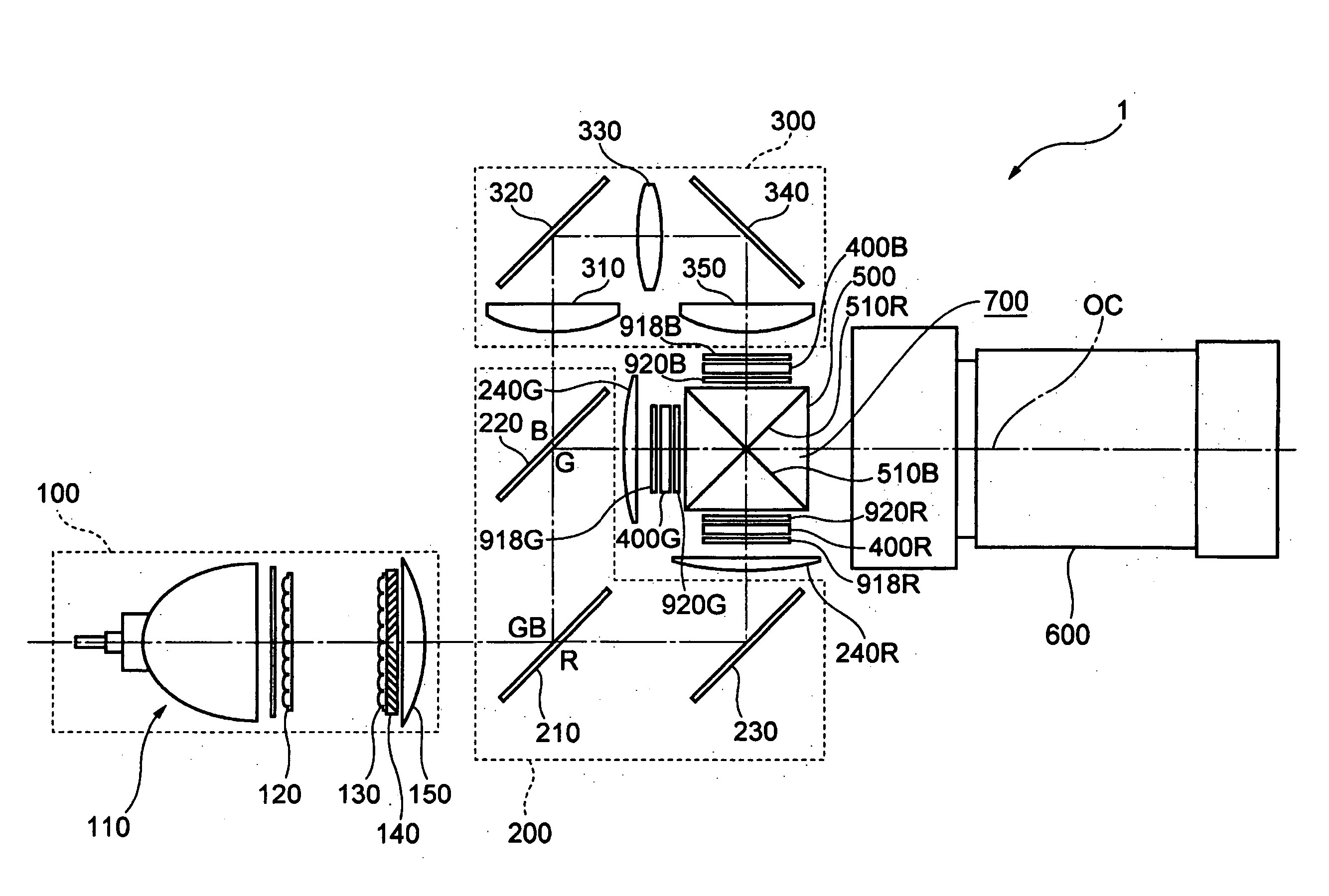
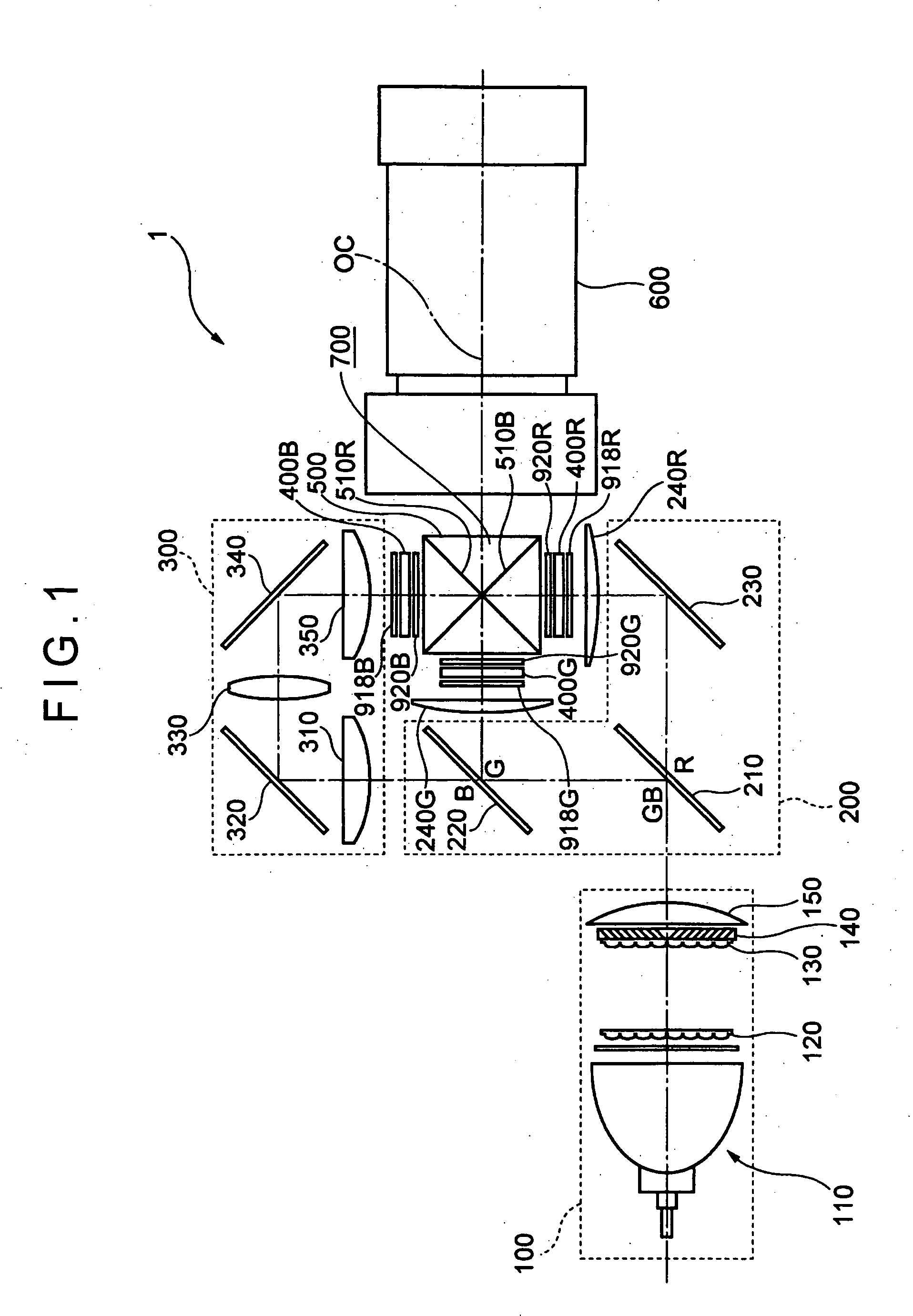
[0043]FIG. 1 is a schematic illustration showing an optical system of a projector 1 provided with an optical device according to the first embodiment.

[0044] The projector 1 modulates a light beam irradiated by a light source in accordance with image information and projects the light beam on a projection surface such as a screen in an enlarged manner. As shown in FIG. 1, the projector 1 includes an illuminating optical system 100, a color-separating optical system 200 as a color-separating optical device, a relay optical system 300, an optical device 700, which has three optical modulators 400R, 400G and 400B and a cross dichroic prism 500 as a color-combining optical system, and a projection optical system 600 as a projection optical device. These optical components 100 to 300, 400R, 400G, 400B, 500 and 600 are hous...

second embodiment

2. SECOND EMBODIMENT

[0116] Next, a second embodiment of the present invention will be described below.

[0117] In the following description, the same reference numerals will be attached to the similar structure and the same components as that of the first embodiment to omit the detailed description thereof.

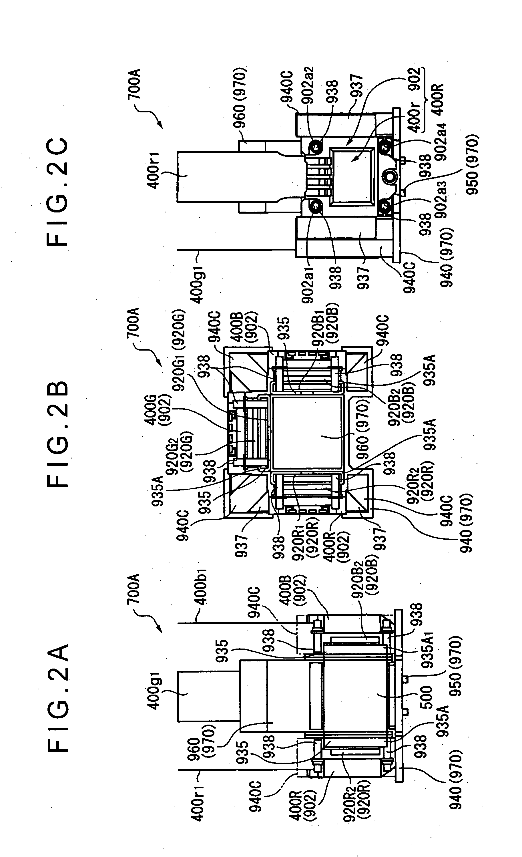
[0118] In the first embodiment, the six reinforcing members 937 are configured by the triangular spacers, which are supported by the columns 940C formed on the heat conductive member 940, and besides support and fix the lateral end surfaces of the panel holder frames 902.

[0119] In contrast, according to the second embodiment, the columns 940C are not provided on a heat conductive member 940′. Further, reinforcing members 937′ are formed by four trapezoidal spacers each having a substantially trapezoidal cross section, the reinforcing members 937′ being supported by the heat conductive member 940′ and also supporting and fixing the lateral end surfaces of the panel holder frames 9...

third embodiment

3. THIRD EMBODIMENT

[0129] Next, a third embodiment of the present invention will be described below.

[0130] In the following description, the same reference numerals will be attached to the similar structure and the same components as that of the first embodiment to omit the detailed description thereof.

[0131] In the first embodiment, the six reinforcing members 937 are configured by the triangle spacers, which are supported by the columns 940C formed at the heat conductive m ember 940, and also support and fix the lateral end surfaces of the panel holder frames 902.

[0132] In contrast, according to the second embodiment (Translator's Comment: correctly, the third embodiment), the columns 940C are not provided at a heat conductive member 940″. Further, a reinforcing member 937″ is formed by rectangular plate processed by sheet metal processing, the reinforcing member 937″ being supported by the heat conductive member 940″ and also supporting and fixing the lateral end surface of th...


PUM


Abstract

A cross dichroic prism 500 as a color-combining optical device and optical modulators 400R, 400G and 400B constituting an optical device body 700A are fixed with insulating pins 938 being interposed. The optical device body 700A includes a base 970 and reinforcing members 937, supporting surfaces for supporting and fixing the reinforcing members 937 are formed at a heat conductive member 940 constituting the base 970. The reinforcing members 937 are supported by the supporting surfaces of the heat conductive member 940, and also support and fix the optical modulators 400R, 400G and 400B so as to enhance fixing state of the optical modulators 400R, 400G and 400B relative to the cross dichroic prism 500. With this arrangement, an optical device as well as a projector, in which connecting state of the optical modulators relative to the color-combining optical device can be strengthened so as to form a fine optical image without pixel deviation, can be provided.

Description

TECHNICAL FIELD [0001] The present invention relates to an optical device and a projector. BACKGROUND ART [0002] Conventionally, there has been known a three-plate type projector including a color-separating optical system that separates a light beam irradiated by a light source into three color lights, three optical modulators that modulate the respective color lights in accordance with image information, and a color-combining optical device that combines the light beam modulated by the respective optical modulators. [0003] In order to downsize the projector, an optical device in which three optical modulators are bonded and fixed relative to a color-combining optical device is applied to such a three-plate type projector (for example, see JP2000-221588A). [0004] In this optical device, the three optical modulators are bonded and fixed relative to the color-combining optical device with a plurality of pin spacers being interposed. [0005] To be more specific, each of the optical mod...

Claims


Application Information

Patent Timeline
Patent Type & Authority Applications(United States)
IPC IPC(8): G02B7/02G03B21/00G03B21/16H04N9/31
CPCH04N9/3105H04N9/3197H04N9/317
Inventor KITABAYASHI, MASASHI
Owner SEIKO EPSON CORP
Why Eureka
Try Eureka