Self-generating flashlight

a self-generating, flashlight technology, applied in the field of flashlights, can solve the problems of wasting energy, wasting energy, and wasting battery resources, and achieve the effect of saving user's cost of batteries, eliminating discarded batteries endangering the environment, and increasing the user's cost of buying batteries

Inactive Publication Date: 2005-04-21
HO PING HUI +1
View PDF5 Cites 14 Cited by
  • Summary
  • Abstract
  • Description
  • Claims
  • Application Information

AI Technical Summary

Benefits of technology

[0006] A further object of the present invention is to provide a self-generating flashlight that includes a generator set to generate power needed by the flashlight to emit light, and therefore does not need an external power supply.
[0007] A still further object of the present invention is to provide a self-generating flashlight that does not require batteries to save a user the cost for batteries, and can therefore be used in humid environments, and does not have the problem of discarded exhausted batteries to endanger the environmental protection.
[0008] A still further object of the present invention is to provide a self-generating flashlight that does not consume any existing energy source, and may be repeatedly used to have an extended usable life.
[0009] The self-generating flashlight of the present invention is particularly suitable for use in an emergency without the risk of lacking or having insufficient battery power.
[0010] Since the flashlight of the present invention does not use any battery, the problems of failing to reserve batteries for a long time or using the batteries in a humid environment, and of discarded batteries endangering the environment can be eliminated. The flashlight of the present invention may be frequently used without consuming existing energy sources or increasing the user's cost of buying batteries. Moreover, the flashlight of the present invention has extended usable life that is not limited by batteries.

Problems solved by technology

The above-structured conventional flashlight A1 has the following drawbacks: (1) it always requires batteries to emit light while the batteries could not be reserved for a prolonged time; (2) the batteries tend to become damaged in a humid environment; (3) the exhausted batteries must discarded that has adverse influence on the environmental protection; (4) the batteries form an additional cost in using the flashlight; (5) the use of chargeable batteries still causes the problem of energy consumption; and (6) the batteries have only very short usable life.

Method used


Image

  • Self-generating flashlight
  • Self-generating flashlight
  • Self-generating flashlight

Examples


Embodiment Construction

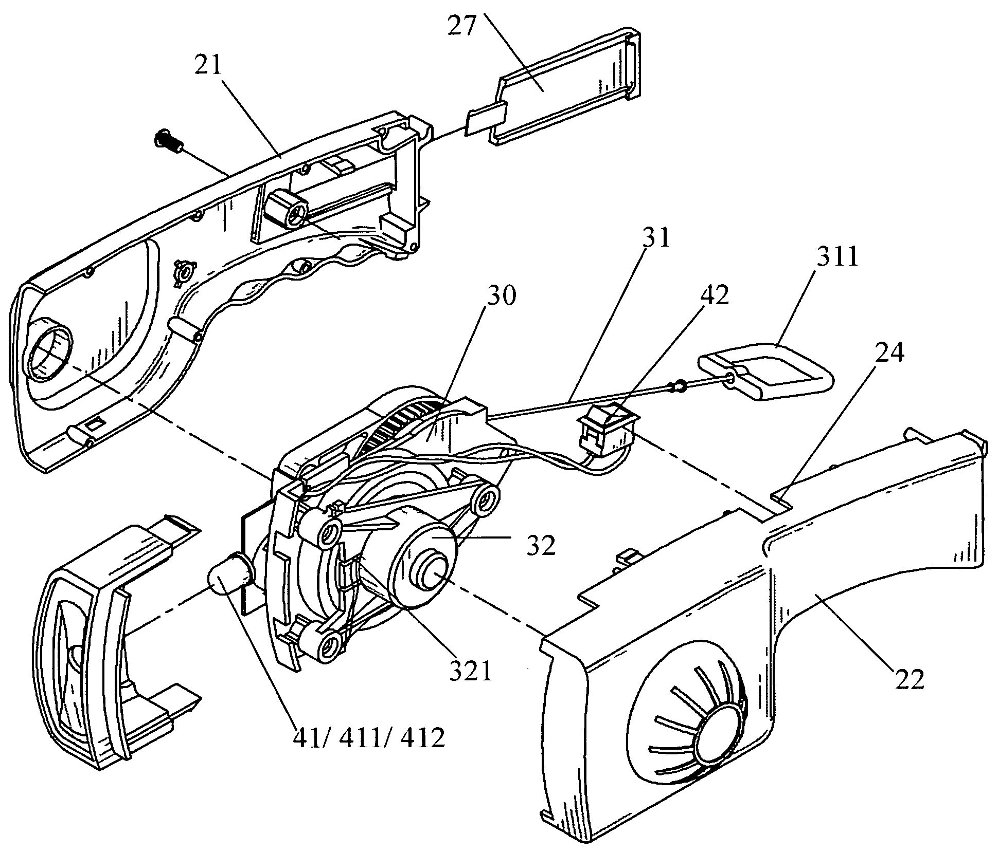
[0025] Please refer to FIGS. 3 and 4 that are assembled and exploded perspective views, respectively, of a self-generating flashlight 10 according to the present invention. As shown, the flashlight 10 includes at least a housing 20, a generator set 30, and a lighting set 40.

[0026] The housing 20 is formed from mated first shell 21 and second shell 22 to define an inner space 23 for accommodating the generator set 30 and the lighting set 40 therein. A control switch opening 24 is provided on the housing 20 at a predetermined position, a lampshade 25 is mounted to a front end of the housing 20, and a rear part of the housing 20 is formed into a handle 26. As can be seen from FIG. 5, a reflection mirror 251 is mounted behind the lampshade 25.

[0027] The generator set 30 is mounted in the inner space 23 defined between the first and the second shell 21, 22, and includes a hand-pulled starter cord 31, an outer end of which is connected to a pull ring 311. The pull ring 311 is normally f...


PUM


Abstract

A self-generating flashlight mainly includes a housing defining an inner space; a generator set accommodated in the inner space of the housing and including a hand-pull starter cord, and a pull ring connected to an outer end of the starter cord; and a lighting set including a light-emitting body, a control switch, and a control circuit, and is electrically connected to the generator set via one or more electric wires. When the pull ring is pulled, the hand-pulled starter cord is drawn to drive the generator set to generate an electric power, which is supplied via the electric wires to the light-emitting body for the latter to emit light.

Description

FIELD OF THE INVENTION [0001] The present invention relates to a flashlight, and more particularly to a self-generating flashlight that transforms an input kinetic energy into an electric energy, and can therefore provides lighting effect without using batteries or an external power supply. BACKGROUND OF THE INVENTION [0002]FIGS. 1 and 2 are assembled and exploded perspective views, respectively, of a conventional flashlight A1. As shown, the conventional flashlight A1 mainly includes a front cap A2, a lens A3, a reflector A4, a bulb A5, a housing A6, more than one battery A7, and a rear cap A8. The batteries A7 supply power needed by the bulb A5 to emit light. When the batteries A7 are low or exhausted, they must be replaced with new ones, lest the bulb A5 should fail to emit light and make the whole flashlight A1 useless. [0003] The above-structured conventional flashlight A1 has the following drawbacks: (1) it always requires batteries to emit light while the batteries could not ...

Claims


Application Information

Patent Timeline
Patent Type & Authority Applications(United States)
IPC IPC(8): F21L4/00F21L13/00
CPCF21Y2101/02F21L13/00F21Y2115/10
Inventor HO, PING-HUICHOU, WEN-LI
Owner HO PING HUI
Why Eureka
Try Eureka