
Mould for tv chassis and tv frames

a technology for tv frames and mouldings, applied in the field of mouldings for television front and rear frames, can solve the problems of inability to change the shape of printed parts, high production costs, and inability to always be satisfactory, and achieve the effect of convenient and intuitive us

Inactive Publication Date: 2005-04-21
B M INDA BERGAMASCA MOBILI
View PDF9 Cites 4 Cited by
  • Summary
  • Abstract
  • Description
  • Claims
  • Application Information

AI Technical Summary

Benefits of technology

[0006] Object of the present invention is to solve the aforesaid drawbacks, providing a mold for front and rear frames of TV sets, screens, etc., such as to allow to produce frames having different size and / or lines, and such as to be also of easy and intuitive use.
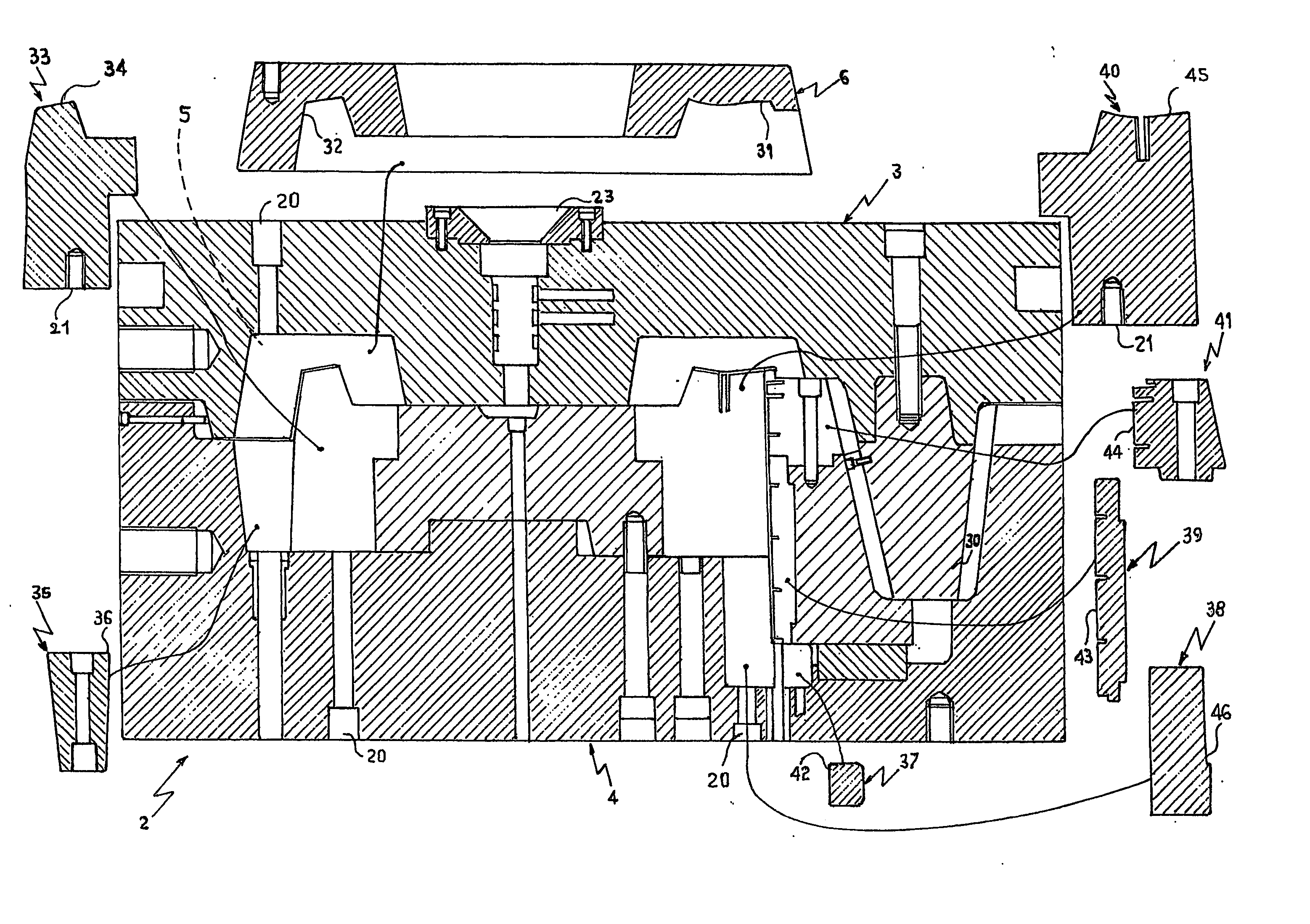
[0009] The above objects and additional advantages are achieved by means of the present invention that relates to a mold for cabinet frames of television sets, monitors, displays and like products, comprising at least a basic mold element and at least a basic counter-mold element that define a cavity, characterized in that it comprises one or more modular inserts / elements at least partly shaped that fill up said cavity movably, to modify the shape and / or size of the part to be molded. In particular, said basic mold element and said basic counter-mold element are completed through the association with one or more of said mold modular element, obtaining thereby one only modular mold that allows the realization of molded parts of different shapes and / or dimensions depending on the shapes of said individual elements to be associated to said basic elements. In this way it is possible to produce with one only mold, frames of different size and / or forms by simply changing the modular inserts / elements. In this way, the investment and production costs reduce, both because it is possible to produce with one only mold frames having different models and size, and because at the end of the product life, which as mentioned above is equal to about two years, the mold can be partly re-utilized through the realization of new and suitable modular inserts, and used for the production of a new product that represents the aesthetic and / or functional evolution of the previous model. As a consequence, there reduces also the time between the design and the marketing of a new product that represents the aesthetic and / or functional evolution of the previous one, achieving, among other results, a strong competition advantage with respect to firms that base their production on construction / utilization methods of traditional molds and molding processes.

Problems solved by technology

Another very important aspect lies in that the form of the printed part cannot be changed unless the whole mold is replaced, which obviously involves economic problems.
Another problem is represented by the necessity of realizing different models that, the sizes being equal, have a variable location of the push button panel and / or the areas intended for housing possible loudspeakers or operation and / or adjustment devices that are usually located on the screen supporting frame.
In this case, in order to prevent the replacement of the mold, the attempt has been at solving the problem by means of suitable “templates”, but the result has not always been satisfactory, and besides this system only allows to perform extremely limited variations.
It is therefore evident that the production of these frame elements is very expensive, requires very high initial investments, and besides it does not allow any changes in the models produced.
The situation appears to be even more critical as generally the cabinet models undergo a very rapid aging.

Method used


Image

  • Mould for tv chassis and tv frames
  • Mould for tv chassis and tv frames
  • Mould for tv chassis and tv frames

Examples


Embodiment Construction

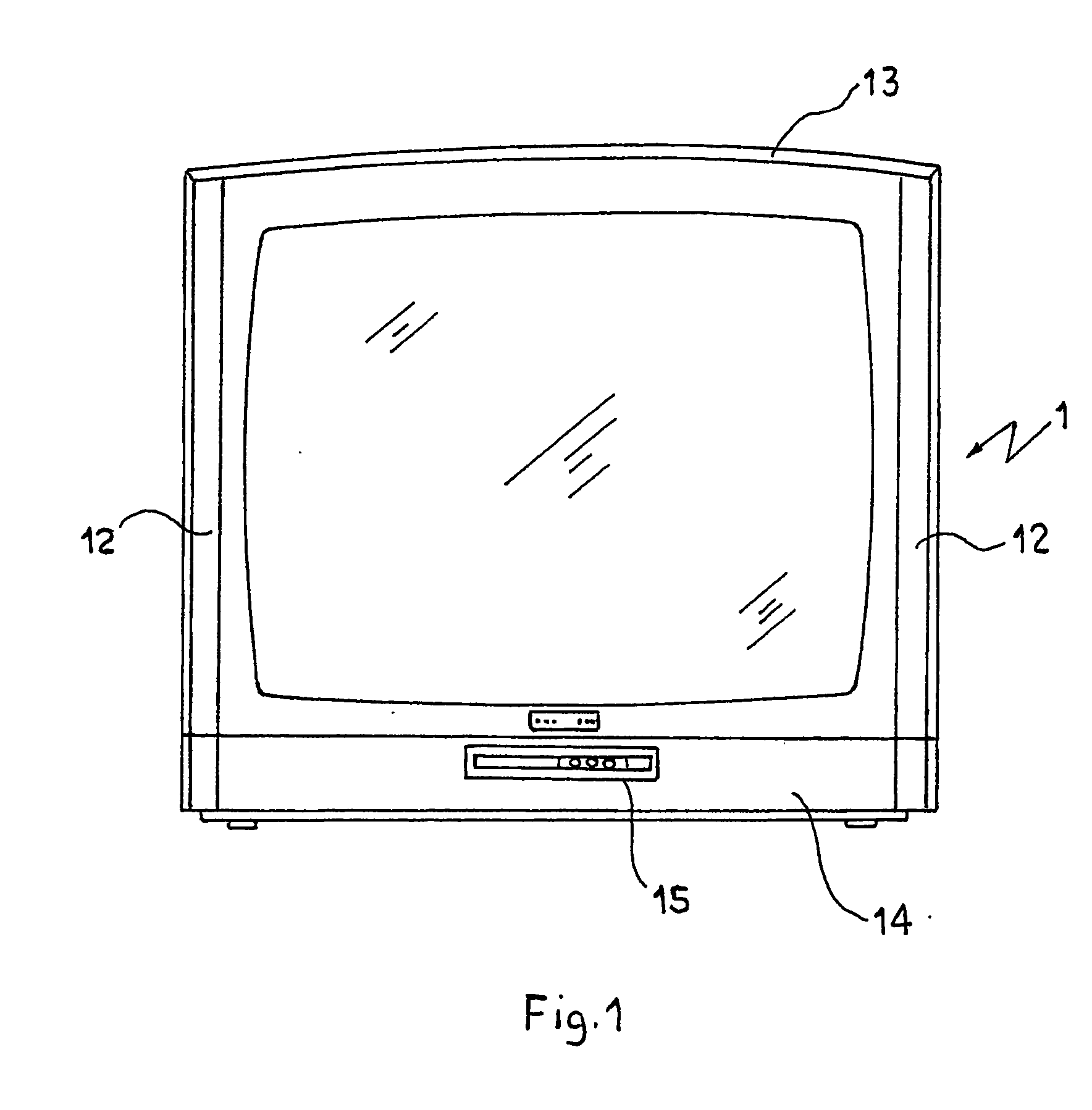
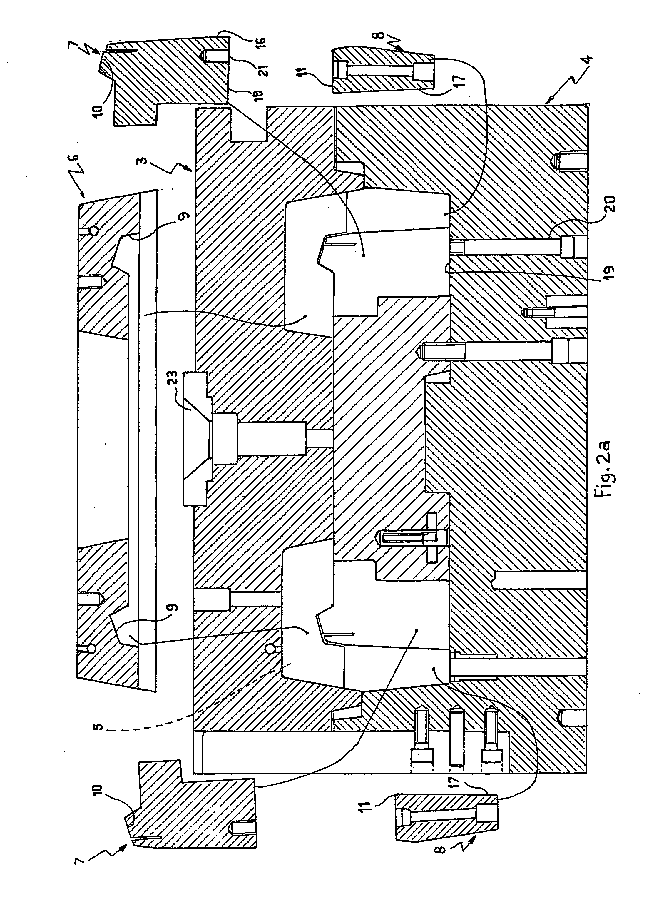
[0019]FIG. 1 shows, by way of example, a product, and in particular the front portion of a frame 1 for TV sets, realizable with a mold 2 according to the present invention. With reference to FIGS. 2, 3, a mold 2 according to the invention comprises a basic element of a fixed mold 3 an a basic element of mobile counter-mold element 4 that define a cavity 5 represented in FIGS. 2 and 3 by the area filled up by the movable modular elements. Said cavity 5 is filled up, for instance, by the shaped modular inserts 6, 7, 8 of FIG. 2a, suitable to define at least partly the part to be molded 1.

[0020] In the present description by the term “cavity” there is not intended to indicate—as in the usual molds—only the molding cavity realized in the basic mold element and / or the basic counter-mold element, that reproduces entirely or partly, as the negative, the product to be molded, but also the cavity filled up by the modular shaped inserts, which in this case reproduce entirely or partly throug...


PUM

PropertyMeasurementUnit
Sizeaaaaaaaaaa
Shapeaaaaaaaaaa

Abstract

A mold for cabinet frames of TV sets, monitors and displays, provided with a basic mold element, a basic counter-mold element and one or more at least partly shaped modular inserts / elements that fill up movably the cavity defined by said basic mold and counter-mold elements, to realize variable shapes or sizes of the part to be molded.

Description

TECHNICAL FIELD [0001] The present invention relates to a mold for plastic materials; more particularly, a mold for the front and rear frames of television sets, monitors, displays and like products. BACKGROUND ART [0002] The supporting frame for displays and the rear frame which, upon assembly thereof, form the external cabinet of the display, are produced by molding plastic materials. The molding of each frame requires a suitable mold as in the sector of television sets, monitors, displays and like products, even small variations in size and model correspond to different products. At present, in fact, in order to realize, for instance, a television set having a 19″ screen, a mold is necessary that will be different from the mold utilized to realize a TV set with a 21″ screen. Therefore, in the sector of TV sets, monitors, displays and the like many molds must be used, at least as many as the models having different screen sizes that are produced. Another very important aspect lies...

Claims


Application Information

Patent Timeline
IPC IPC(8): B29C33/30B29C45/26
CPCB29C45/2673B29C33/306
Inventor SCOTTI, LUCA
Owner B M INDA BERGAMASCA MOBILI
Learn More