Subcutaneous vascular access port, and method of using same

a technology of vascular access port and subcutaneous vascular port, which is applied in the direction of medical devices, other medical devices, etc., can solve the problems of obstructing or even blocking the fluid flow through the catheter, floating in the bloodstream uncontrollable, and the number of complications can aris

Inactive Publication Date: 2005-04-21
PARKS ROBERT A
View PDF18 Cites 123 Cited by
  • Summary
  • Abstract
  • Description
  • Claims
  • Application Information

AI Technical Summary

Benefits of technology

[0021] The present invention provides an improved implantable access port, having a main port body with an internal chamber formed therein, in which the internal chamber is configured to readily receive a guide wire therein, and to direct the tip of the guide wire to an outlet. Optionally, the chamber in the main port body may be formed in a directionally aimed conical shape, similar to the shape of a bubble pipe bowl, or an old-fashioned ear trumpet. The central axis of the chamber curves approximately ninety degrees from the inlet to the outlet of the access port.

Problems solved by technology

This sheath can obstruct or even block fluid flow through the catheter.
It has been discovered that during the conventional procedure described above, a number of complications can arise.
The wire loop portion of the loop snare can be sharp, and if it is tightened too aggressively, the wire loop can cut off the tip of the catheter, which then floats uncontrolled in the bloodstream.
Another complication can arise while withdrawing the loop snare, because the distal end of the catheter may break off, in response to pulling pressure, instead of releasing the sheath.
The broken catheter tip then becomes a floating hazard in the bloodstream.

Method used


Image

  • Subcutaneous vascular access port, and method of using same
  • Subcutaneous vascular access port, and method of using same
  • Subcutaneous vascular access port, and method of using same

Examples


Embodiment Construction

[0045] Throughout the present specification, relative positional terms like ‘upper’, ‘lower’, ‘front’, ‘rear’, ‘top’, ‘bottom’, ‘horizontal’, ‘vertical’, and the like are used to refer to the orientation of the apparatus as shown in the drawings. These terms are used in an illustrative sense to describe the depicted embodiments, and are not meant to be limitative. It will be understood that the depicted apparatus may be placed at an orientation different from that shown in the drawings, such as inverted 180 degrees or transverse to that shown, and in such a case, the above-identified relative positional terms will no longer be accurate. In fact, while the access port hereof is shown and discussed in one possible orientation thereof, it will be understood that when surgically installed in a patient, the access port may be oriented differently from the orientation shown in some of the Figures.

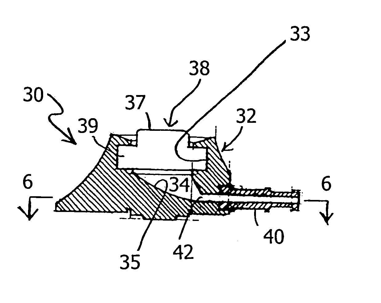
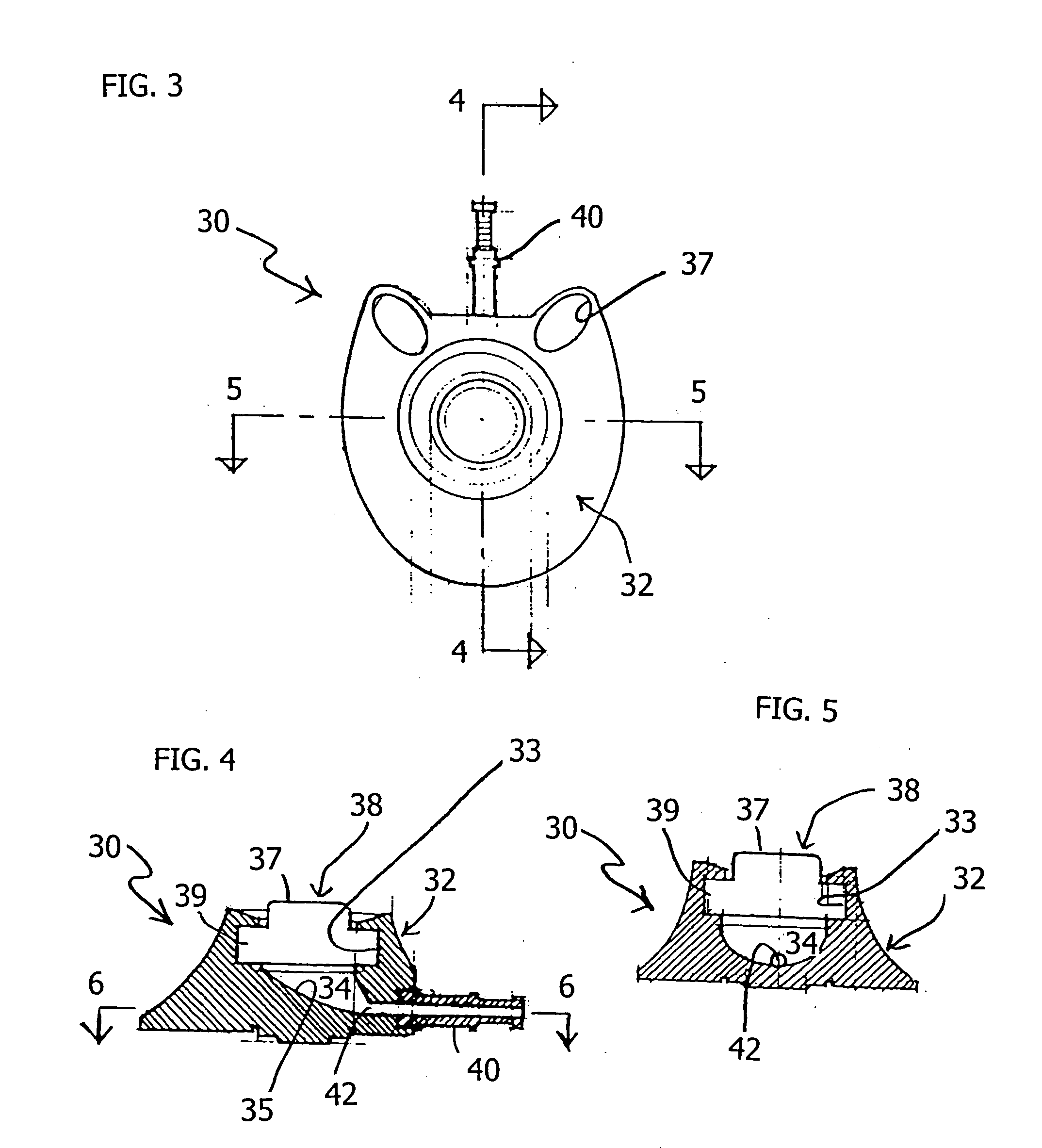
[0046] Referring now to FIGS. 3-6, an implantable access port apparatus, according to a sele...


PUM


Abstract

A surgically implantable access port has a main port body with an internal chamber formed therein, and an outlet tube connected to the main port body. The internal chamber is configured to readily receive a guide wire therein, and to passively direct the tip of a guide wire to an outlet, which is in fluid communication with the outlet tube. The chamber in the main port body is formed in a directionally aimed conical shape. The outlet may be located at the lowest area of the chamber, to help direct a guide wire thereto. A specialized needle is also described, having a curved tip with an opening formed therein. The top inner and the and the bottom outer surfaces of the needle, adjacent the tip opening, are rounded and non-sharp to avoid damaging a guide wire when used therewith. Methods of using the port and needle are also disclosed.

Description

CROSS-REFERENCE TO RELATED APPLICATIONS [0001] The present invention claims priority under 35 USC 119 based on U.S. provisional patent application No. 60 / 511,152, filed Oct. 14, 2003. The complete disclosure of the referenced provisional application is incorporated herein by reference.BACKGROUND OF THE INVENTION [0002] 1. Field of the Invention [0003] The present invention relates to implantable subcutaneous vascular access ports, for implanting beneath the skin of a patient, and for allowing vascular access for medicines to be repeatedly injected into a patient, or for drawing blood, without damaging the access site. More particularly, the present invention relates to a subcutaneous vascular access port having a uniquely-shaped internal chamber therein. [0004] 2. Description of the Background Art [0005] A number of different implantable subcutaneous vascular access ports are known, for allowing a medical professional to repeatedly inject medicine into a patient over time. This is u...

Claims


Application Information

Patent Timeline
Patent Type & Authority Applications(United States)
IPC IPC(8): A61M31/00A61M39/02
CPCA61M39/0208
Inventor PARKS, ROBERT A.
Owner PARKS ROBERT A
Why Eureka
Try Eureka