Temporary blood circulation assist device

a technology of assist device and blood circulation, which is applied in the field of temporary blood circulation assist device, can solve the problems of inability inability to maintain constant blood pressure, and inability of iabp to create blood pressure, so as to prevent laceration, perforation and possible collapse

Inactive Publication Date: 2006-01-03
RUTGERS THE STATE UNIV
View PDF5 Cites 262 Cited by
  • Summary
  • Abstract
  • Description
  • Claims
  • Application Information

AI Technical Summary

Benefits of technology

[0024]The present invention intends to provide an axial flow blood circulation assist device that can be delivered as a compact package through a 10 French (or smaller) arterial or venous sheath(s) under fluoroscopy or transthoracic echocardiogram, and then expanded when positioned in the desired operational location. The present invention may be designed as a temporary device in emergent and surgical situations where time is of the essence. One preferred embodiment may be...

Problems solved by technology

Certain medical conditions, traumas, and surgeries result in a patient's heart not being able to maintain adequate blood pressure to perfuse the patient's organ systems and tissues.
An IABP, however, cannot create blood pressure when there is no left ventricle function, or during severe arrhythmia or fibrillation.
Further, IABPs, in general, typically operate on a pulsate basis, and do not maintain constant blood pressure throughout the heart cycle.
Moreover, IABPs typically use helium as the drive gas for the balloon and some require complex control systems....

Method used


Image

  • Temporary blood circulation assist device
  • Temporary blood circulation assist device
  • Temporary blood circulation assist device

Examples


example i

Aortic Valve Placement

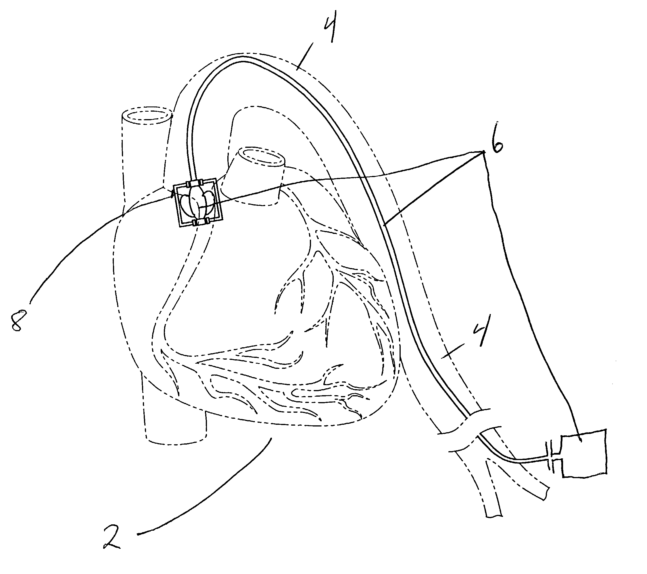
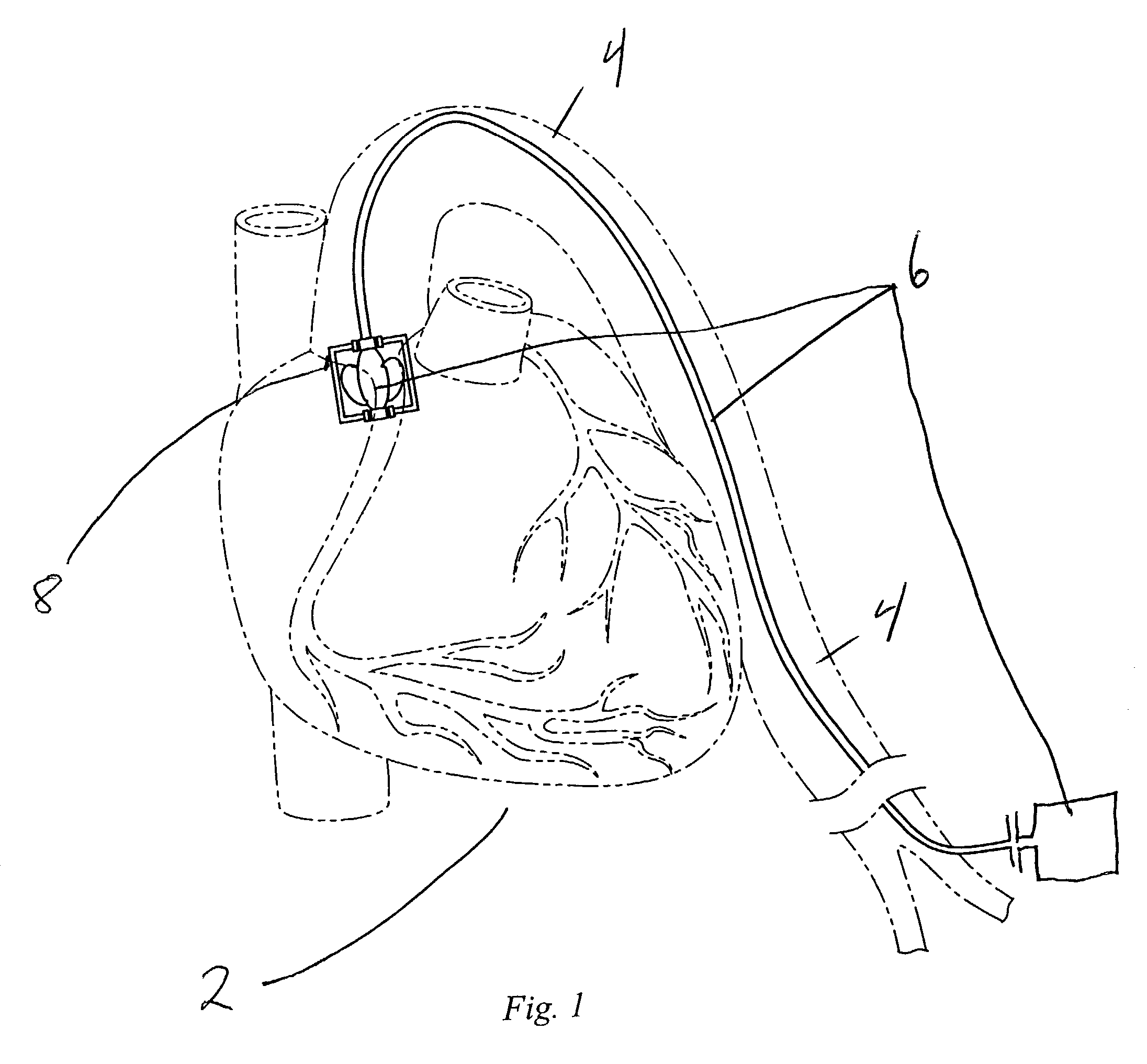
[0060]A patient suffers the effects of left ventricular dysfunction and a procedure using the described invention may be chosen. The patient may be prepared for the procedure in the customary manner. The femoral artery approach may be chosen and the circulation assist device may be advanced to the aortic valve. The described circulation assist device may be then placed across the aortic valve to provide blood to the body due to the left ventricular dysfunction. The stator housing may be positioned across the aortic valve after the stator housing exterior has been adapted to fit that particular patient's aortic valve, with the valve size determined by ultrasound measurement or other suitable means. Here, the stator housing may be adapted to sit across the aortic valve in which the anulus fibrosus may measure greater than 3 cm. A two blade semi-lunar impeller may be chosen. The pitch of the blades may be between 15 and 20 degrees. The stator housing may be positi...

example ii

Pulmonic Valve Placement

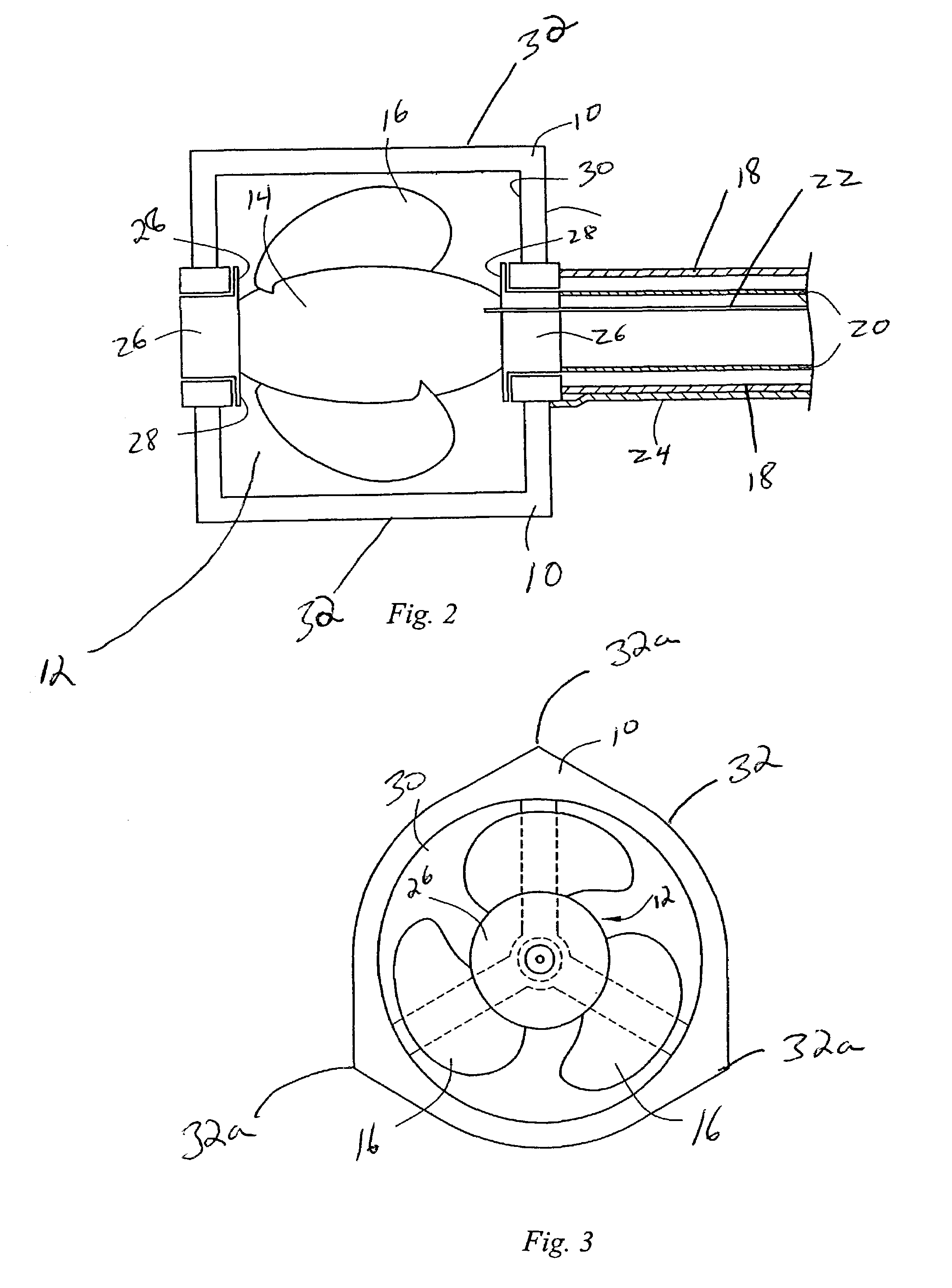
[0062]Due to right ventricular dysfunction, it may be desirable to use the invention across the pulmonic valve. The procedure may be performed as above. Here, the direction of impeller rotation may be used to draw blood either into our out of the right ventricle. Blood may be pulled from the heart towards the proximal aspect of the circulation assist device and moved across the pulmonary valve. The metal coil in the first drive shaft may be rotated in the reverse direction, and impeller 12 may be adapted to operate in the reverse direction. Alternatively the impeller may be rotated in the same direction as in the aortic valve embodiment with impeller blades reversed and adapted to move blood in the opposite direction. A one-way valve may also be employed. In this case, it may be desirable to select a tow-blade impeller with a classic tear drop shape. A pitch of 15–20 degrees may be selected and the RPM chosen at between 700–2000 RPM. A flow rate of 1.8 L / min ...


PUM


Abstract

An inflatable circulation assist device is disclosed consisting of an inflatable stator housing an impeller with inflatable blades of varying shapes and sizes. The invention is introduced into the patient percutaneously. The circulation assist device is a small pump packaged into a compact form that is attached to a long flexible driveshaft. The pump is inserted along a guidewire to a target location, and then the pump is inflated. The circulation assist device's exterior is designed to expand only so much as to closely fit whatever cardiovascular system element in which it is placed for operation. The vascular assist device can be expanded either by inflation with a fluid. The driveshaft, which connects to the circulation assist device's impeller and extends outside the patient's body, is rotated by an external motor. After the circulation assist device is no longer needed, it is collapsed into a compact form and removed from the patient percutaneously.

Description

CLAIM OF PRIORITY[0001]This application claims priority to U.S. Provisional Application No. 60 / 331,909 filed on Nov. 19, 2001 which is incorporated as if fully set forth herein.FIELD OF THE INVENTION[0002]The present invention relates to the field of blood circulation assist devices.BACKGROUND OF THE INVENTION[0003]Certain medical conditions, traumas, and surgeries result in a patient's heart not being able to maintain adequate blood pressure to perfuse the patient's organ systems and tissues. Medical advances in circulation assist devices focus on this area wherein the heart or part of the heart is not able to contract and relax with the force necessary to maintain blood flow and pressure. These devices have been referred to ventricular assist devices, or “VAD.” One specific type of VAD is a left ventricular assist device, or “LVAD.”[0004]In the simplest of terms, the right ventricle of the heart receives blood from the right atrium. The blood from the right atrium has come from th...

Claims


Application Information

Patent Timeline
IPC IPC(8): A61M1/12A61M60/178A61M60/237A61M60/414A61M60/808A61M60/825
CPCA61M1/101A61M1/125A61M1/1034A61M1/1024A61M60/414A61M60/808A61M60/237A61M60/825A61M60/13A61M60/135A61M60/148A61M60/178
Inventor KHAW, KENNETHLI, JOHN K-J
Owner RUTGERS THE STATE UNIV
Why Eureka
Try Eureka