Stent delivery device

a technology of stent and stent body, which is applied in the field of stent delivery devices, can solve the problems of weak bending strength of the coupling part between the pusher tube and the stent, inability to perform treatment, and disadvantageous leakage of liquid from the insertion hol

Inactive Publication Date: 2005-04-21
OLYMPUS CORP
View PDF12 Cites 107 Cited by
  • Summary
  • Abstract
  • Description
  • Claims
  • Application Information

AI Technical Summary

Benefits of technology

[0019] According to the present invention, a stent delivery device included a stent, a guide member having an inner cavity, at least a distal end portion of the guide member being insertable in the stent, a pulling member including an engaging portion that is inserted in a gap between the inner cavity of the stent and the guide member and detachably engages the stent, and an insertion portion that passes through at least a part of the inner cavity of the guide member, the pulling member executing an operation for pulling the stent when the engaging portion engages the stent, and an engagement-releasing member that moves the pulling member in an axial direction of the guide member, thereby releasing the engagement between the engaging portion and the stent.

Problems solved by technology

Consequently, even if a subsequent treatment is to be performed using the guide wire as a guide after the stent is positioned, such a treatment cannot be performed.
Since the coupling part between the pusher tube and stent is kept in such a state that the end faces of the pusher tube and stent are merely abutted on each other, the bending strength of the coupling part between the pusher tube and stent is weak.
Consequently, when the pusher tube is advanced in the procedure for positioning the stent in the stenotic part, buckling may occur at the coupling part between the pusher tube and the stent, and the stent may not be approached to a target part.
Consequently, when a liquid is fed through the pusher tube, the liquid may disadvantageously leak from the insertion hole.

Method used


Image

  • Stent delivery device
  • Stent delivery device
  • Stent delivery device

Examples


first embodiment

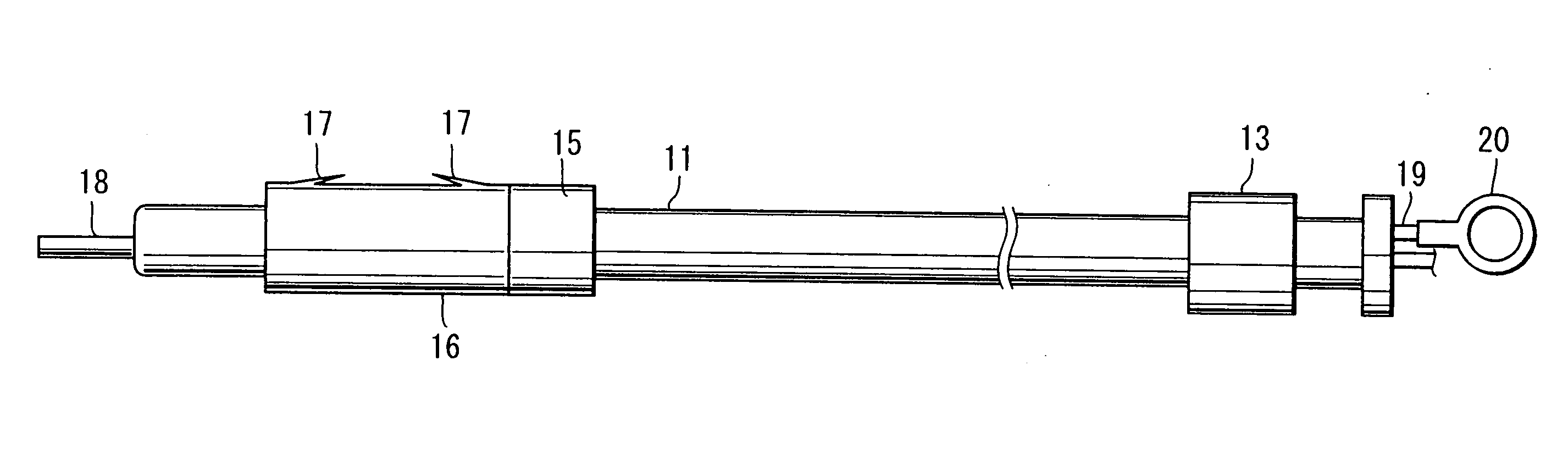
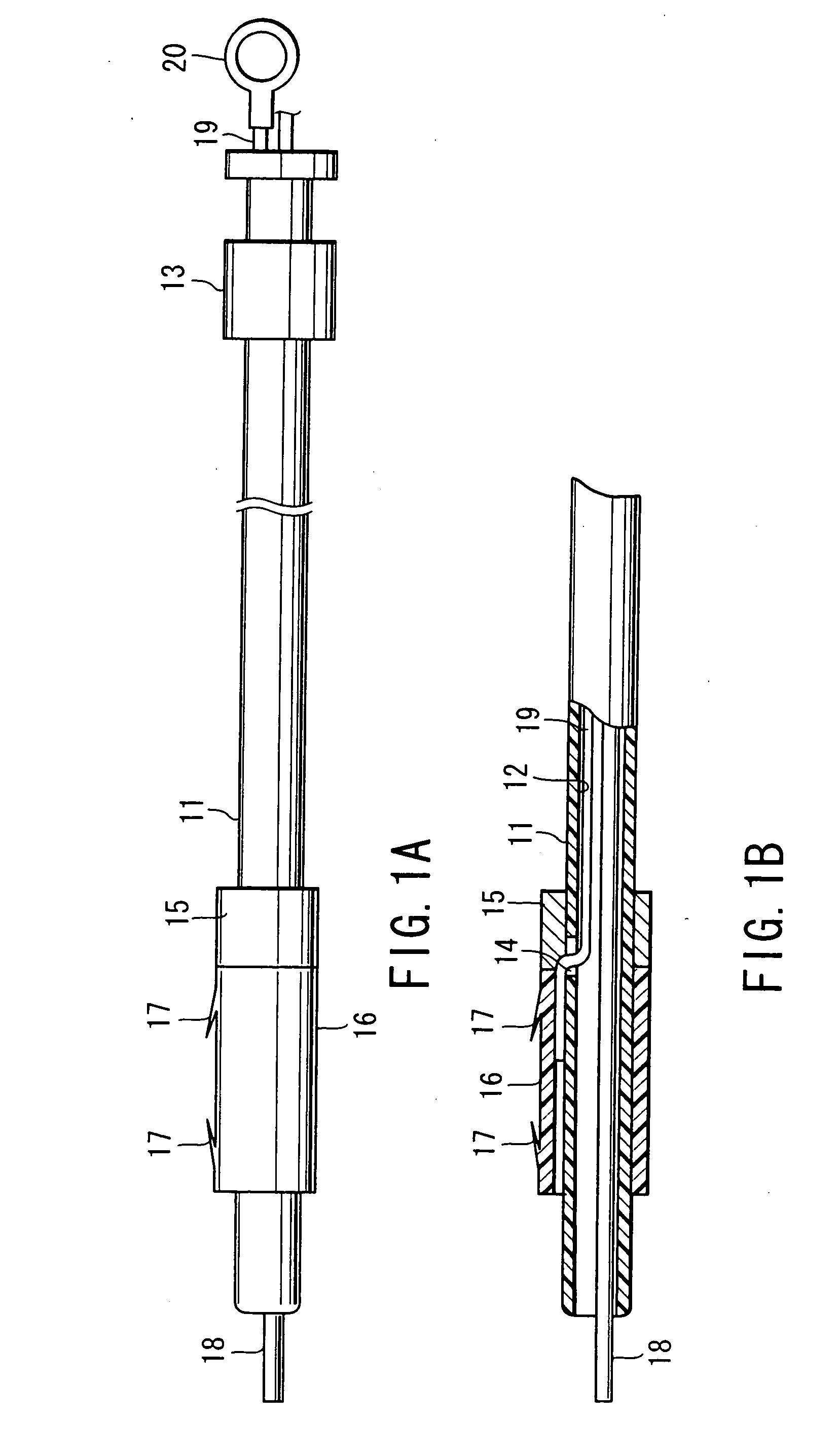
[0075]FIG. 1A and FIG. 1B show a stent delivery device according to a

[0076] As is shown in FIG. 1A, the stent delivery device according to the present embodiment is provided with an elongated guide catheter 11 that is insertable in a forceps channel of an endoscope (not shown). The guide catheter 11 is formed of a flexible synthetic resin material such as a fluoro-resin or a nylon resin. An inner cavity 12 is formed in the guide catheter 11 over the entire length thereof. A guide catheter cock 13 is provided near a proximal end portion of the guide catheter 11.

[0077] As is shown in FIG. 1B, a single small hole 14 is formed in a side wall of the guide catheter 11 near a distal end portion of the guide catheter 11. A fixing ring 15, which is an enlarged part with a large outside diameter, is fitted on the outer peripheral surface of the guide catheter 11 at a position corresponding to the small hole 14. The fixing ring 15 is disposed so as to close part of the small hole 14.

[0078] I...

second embodiment

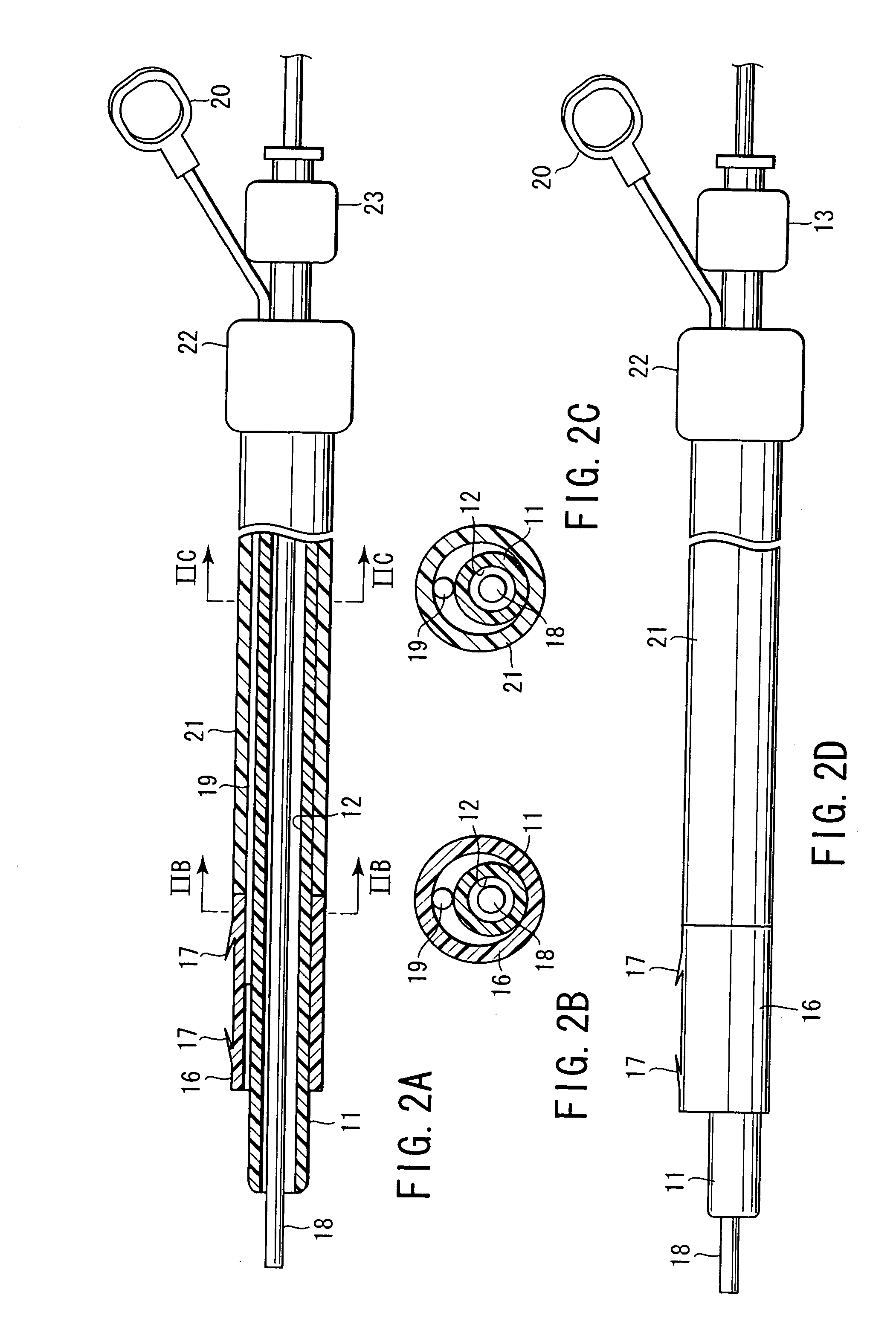
[0103] Next, the operation of the stent delivery device is described. When the stent delivery device according to this embodiment is used, the stent delivery device is set as follows.

[0104] To begin with, the flexible wire 19 is passed between the guide catheter 11 and the pusher tube 21 of the stent delivery device. Then, the stent 16 is fitted on the distal end portion of the guide catheter 11. Subsequently, the distal end portion of the flexible wire 19 is press-fitted between the stent 16 and guide catheter 11. Thus, as shown in FIG. 2A, the guide catheter 11, stent 16, flexible wire 19 and pusher tube 21 are set in the assembled state.

[0105] Thereafter, like the first embodiment, the guide wire 18 is passed through the forceps channel of the endoscope. Then, the operation for guiding the stent 16 to the stenotic part of the bile duct by means of the guide catheter 11 is performed. This method is the same as in the first embodiment. In the present embodiment, the stent 16 is i...

fourth embodiment

[0123] Next, the operation of the fourth embodiment is described. When the stent delivery device according to this embodiment is used, the stent delivery device is set as follows.

[0124] To begin with, the flexible wire 19 is inserted in the inner cavity of the pusher tube 24, and the distal end portion thereof is led out of the passage hole 25 to the outside of the small-diameter portion 24a. Then, the stent 16 is fitted on the distal-end small-diameter portion 24a of the pusher tube 24. Further, as shown in FIG. 4B, the distal end portion of the flexible wire 19 is press-fitted between the inner peripheral surface of the stent 16 and the outer peripheral surface of the small-diameter portion 24a. Thus, as shown in FIG. 4A, the pusher tube 24, stent 16 and flexible wire 19 are set in the assembled state.

[0125] The guide wire 18 is passed through the forceps channel of the endoscope, and the stent 16 is guided to the stenotic part of the bile duct by means of the pusher tube 24 in t...


PUM


Abstract

A stent delivery device includes a stent, a guide member, a pulling member including an engaging portion that is inserted in a gap between an inner cavity of the stent and the guide member and detachably engages the stent, and an insertion portion that passes through an inner cavity of the guide member, the pulling member executing an operation for pulling the stent when the engaging portion engages the stent, and an engagement-releasing member that releases engagement between the engaging portion and the stent.

Description

CROSS-REFERENCE TO RELATED APPLICATIONS [0001] This is a Continuation Application of PCT Application No. PCT / JP03 / 05581, filed May 1, 2003, which was published under PCT Article 21(2) in Japanese. [0002] This application is based upon and claims the benefit of priority from prior Japanese Patent Applications No. 2002-129961, filed May 1, 2002; and No. 2002-133127, May 8, 2002, the entire contents of both of which are incorporated herein by reference.BACKGROUND OF THE INVENTION [0003] 1. Field of the Invention [0004] The present invention relates to a stent delivery device that is used at a time of performing an operation for inserting a stent into a body cavity of a patient using an endoscope and positioning it there. [0005] 2. Description of the Related Art [0006] For example, the following treatment is performed to exhaust bile, etc., which is present in the bile duct. A stent is guided to a stenotic part of the bile duct through a channel of an endoscope. Thus, the stent is posit...

Claims


Application Information

Patent Timeline
Patent Type & Authority Applications(United States)
IPC IPC(8): A61F2/04A61F2/94
CPCA61F2/94A61F2/95A61F2002/9511A61F2002/9505A61F2002/041
Inventor GOTO, HIROAKIKOMIYA, TAKAAKIINOUE, YOSHIMITSU
Owner OLYMPUS CORP
Why Eureka
Try Eureka