
Music tuner

Inactive Publication Date: 2005-04-28
KORG
View PDF8 Cites 40 Cited by
  • Summary
  • Abstract
  • Description
  • Claims
  • Application Information

AI Technical Summary

Benefits of technology

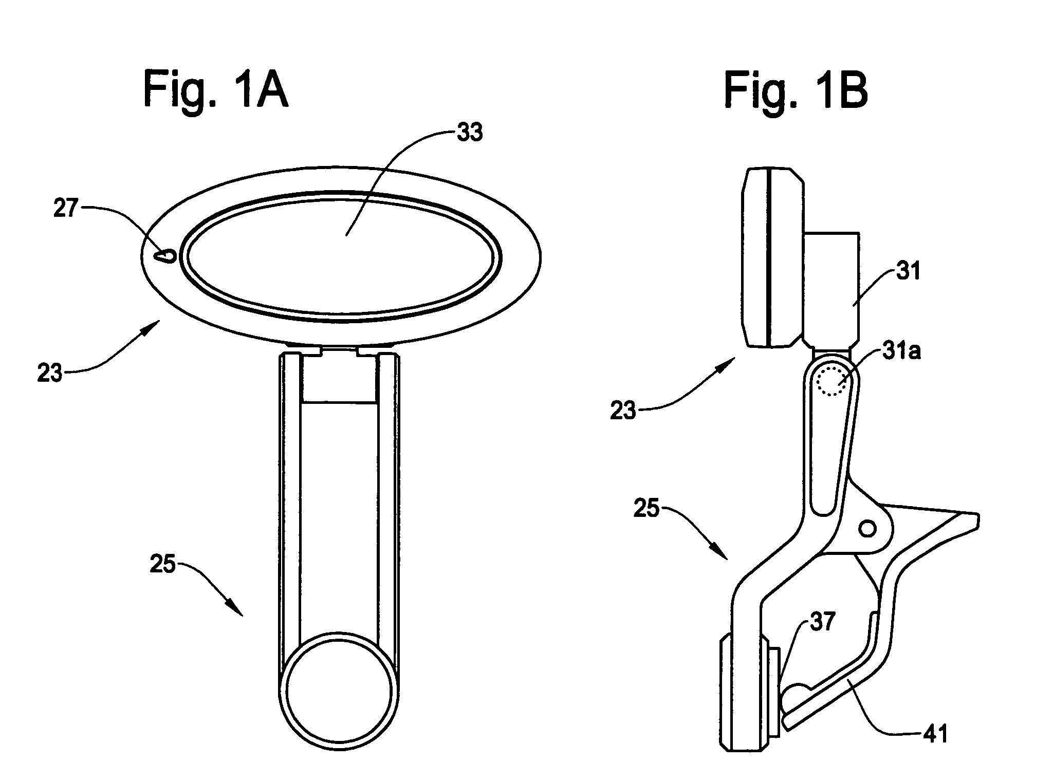
[0009] It is another object of the present invention to provide a music tuner which is capable of detaching a part having the contact sensing device (piezo device) from the music tuner so that the tuner functions separately and independently from the piezo device.
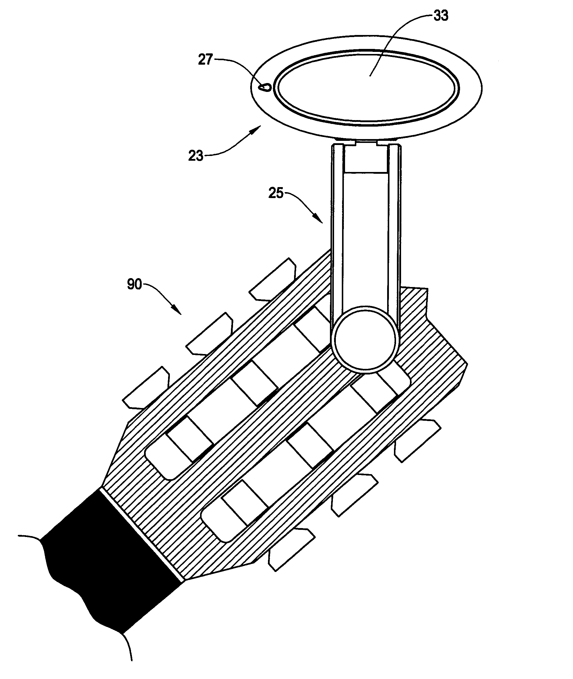
[0010] It is a further object of the present invention to provide a music tuner which is capable of achieving high flexibility by allowing a tuner body having a display to freely pivot and rotate so that the user can see the display with an optimal viewing angle and direction.
[0012] It is a further object of the present invention to provide a music tuner which is able to display a combined music pitch which simultaneously shows both a normal display mode display and a mirror display mode such that the indicators move toward the center as the sound from the music instrument comes closer to the target sound.
[0018] According to the present invention, because the music tuner can automatically select the appropriate sound sensing device, the user need not worry about which sensing device to select. The user merely needs to attach the tuner to the music instrument. Because the tuner body is pivotable and rotatable, the user can enjoy an optimum viewing angle and condition. The mirror display function allows the user to obtain intuitive display image even when the specific circumstance forces the user to attach the tuner that would otherwise show the indicator in a reverse direction, etc.

Problems solved by technology

The sounds from other instruments can diminish the accuracy of the music tuner utilizing a microphone because the microphone of the turner can pick the ambient sounds as well.
Depending on a type of musical instrument, attaching the music tuner so that a sensing device can detect the sound of the instrument may be difficult or impractical.
In some cases, the user just prefers to use the microphone because ambient sound is negligible or attaching the music tuner to the music instrument is cumbersome.
Moreover, in a conventional music tuner using a piezo device, it may become difficult to read the display of the music tuner when it is attached to a specific location of the music instrument.

Method used


Image

  • Music tuner
  • Music tuner
  • Music tuner

Examples


Embodiment Construction

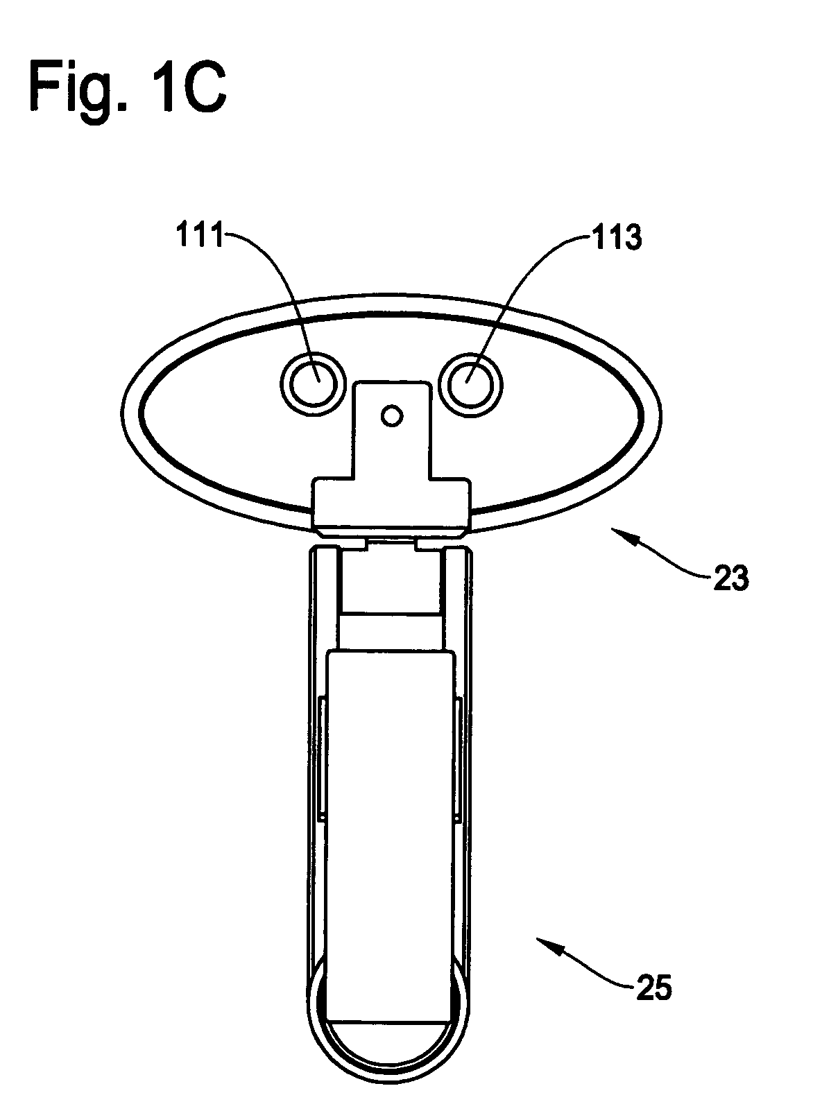
[0034] The present invention is explained with reference to the accompanied drawings. The music tuner of the present invention incorporates both the contact sensing device, typically a piezo device, and the non-contact sensing device, typically a microphone, to effectively take advantage of the benefits of both types of sensing device while maximizing the display flexibility and minimizing the complexity of use.

[0035] In order to increase the usefulness, the music tuner of the present invention automatically selects either the microphone (non-contact sensing device) or the piezo device (contact sensing device). The music tuner of the present invention also includes a switch to manually selects either the microphone or the piezo device by the user. Thus, the user can set either the automatic mode or the manual mode depending on her unique situation.

[0036] The music tuner of the present invention has a tuner body which is freely rotatable, thereby allowing optimum view angle whereve...


PUM


Abstract

A music tuner having both a contact sensing device and a non-contact sensing device to pick up the sound from a music instrument is so designed that it can automatically or manually select one of the sensing devices that is most suitable to the situation where the music tuner is used. The display screen of the music tuner is freely rotatable and pivotable, thereby allowing optimum view angle wherever the music tuner is placed. The display screen is configured to graphically represent the tune of the music instrument so that the user can easily and intuitively grasp the pitch of the sound as compared with a standard pitch. The music tuner is able to display the result by a normal display mode, a mirror display mode, or a combination of both modes.

Description

FIELD OF THE INVENTION [0001] This invention relates to a music tuner to tune music instruments. More particularly, this invention relates to a music tuner to tune music instruments which is able to automatically select a suitable sensing device from either a non-contact sensing device or a contact sensing device to pick-up sounds to be tuned and allows the user to easily see the display of the tuner regardless of a manner that the music tuner is attached to a music instrument, etc. BACKGROUND OF THE INVENTION [0002] A tuning device for music instrument (hereafter “music tuner”) is widely used to measure and adjust the pitch of a sound of a music instrument. Basically, a music tuner measures a frequency of a musical sound to allow the user to adjust the sound to a predetermined frequency. [0003] There are primarily two kinds of music tuners widely available in the market in terms of the type of music sound sensing device. One type of the music tuner has a non-contact sensing device,...

Claims


Application Information

Patent Timeline
IPC IPC(8): G10G7/02
CPCY10S84/18G10G7/02
Inventor TAKU, TAKEOHIGO, KOUSUKE
Owner KORG
Learn More