Method of and apparatus for cleaning runoff water

a runoff water and runoff technology, applied in the direction of liquid displacement, multi-stage water/sewage treatment, separation process, etc., can solve the problems of significant amount of trash, debris, other floatable materials entrained in the water, and the treatment capacity of the plant can exceed the capacity, so as to prevent contamination

Inactive Publication Date: 2005-04-28
PANK THOMAS E
View PDF19 Cites 9 Cited by
  • Summary
  • Abstract
  • Description
  • Claims
  • Application Information

AI Technical Summary

Benefits of technology

[0013] The skirt portion has a funnel in it which causes the water from the swirl to speed up and then expand when it leaves the funnel and passes into the settling chamber. The aforesaid increase in speed followed by an expansion further tends to separate the contaminants from the water.
[0014] A shelf in the settling chamber acts as means for preventing the swirling water from resuspending any accumulated material in the settling chamber.
[0016] The permeable barriers which clean the water have a series of louvers projecting from the permeable barriers at acute angles to the direction of flow (See FIG. 9). This enables the louvers to prevent contaminants from blocking the permeable barrier.

Problems solved by technology

These systems function perfectly well when the weather is dry, but have the potential to overflow during large storms.
Because wastewater treatment plants are designed to handle limited flows, even frequently recurring storms have the potential to exceed the treatment capacity of the plant.
These systems, while effective at low flow rates, often include a bypass structure that allows high flows to pass through or around the system untreated.
Although the runoff during intense storms usually has lower concentration of pollutants like sediments, nutrients, and oils, there is often a significant amount of trash, debris, and other floatable material entrained in the water.

Method used


Image

  • Method of and apparatus for cleaning runoff water
  • Method of and apparatus for cleaning runoff water
  • Method of and apparatus for cleaning runoff water

Examples


Embodiment Construction

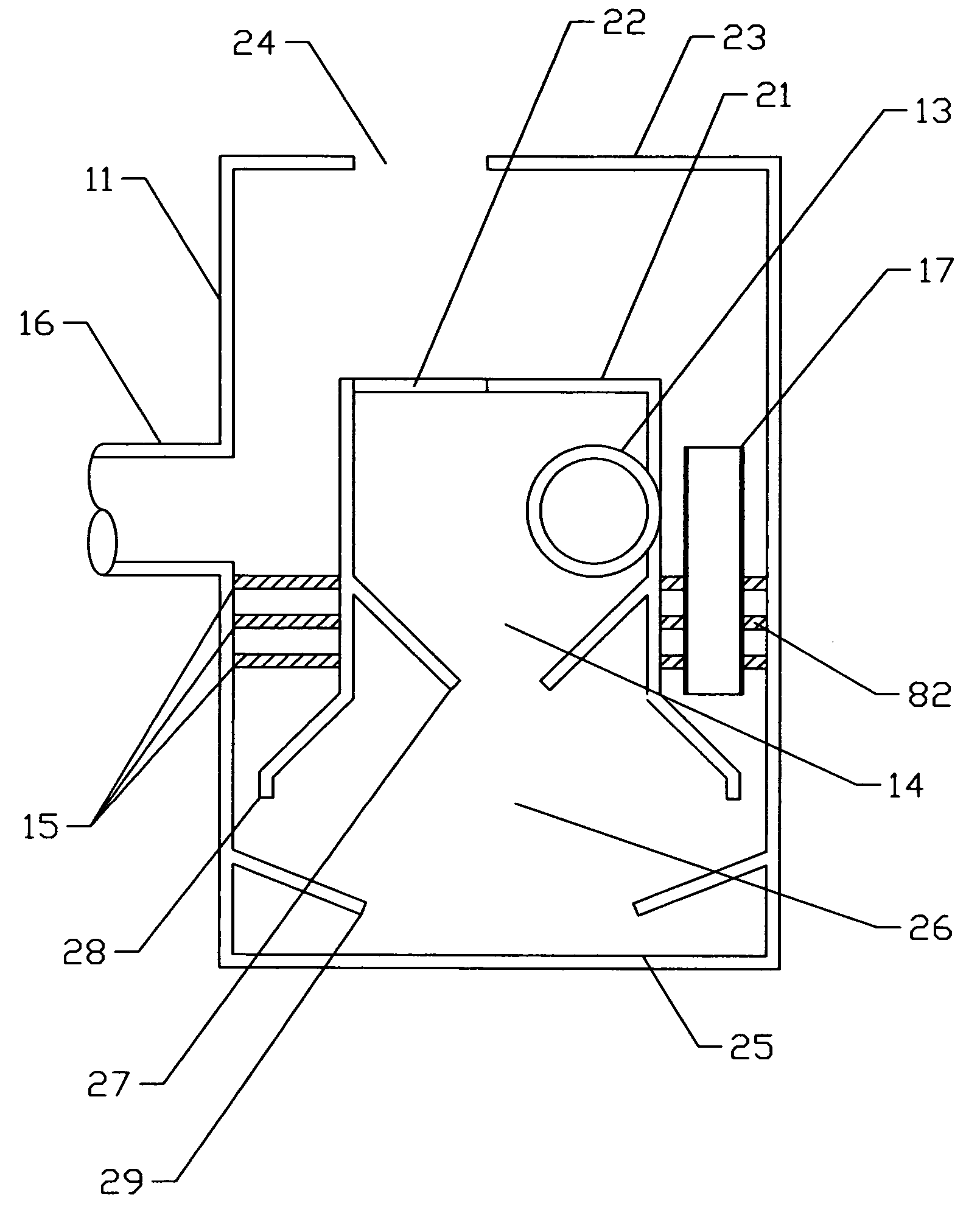
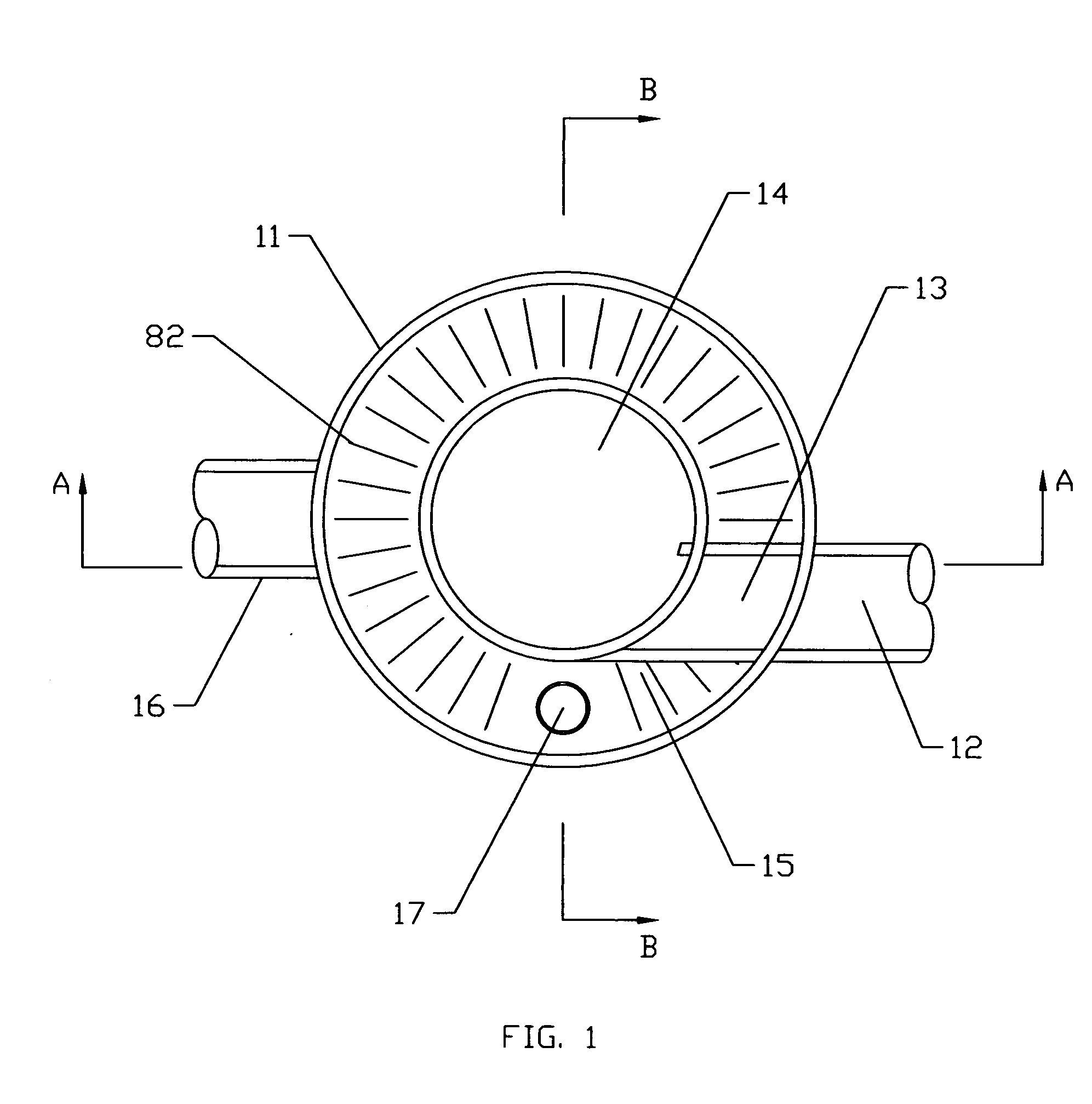
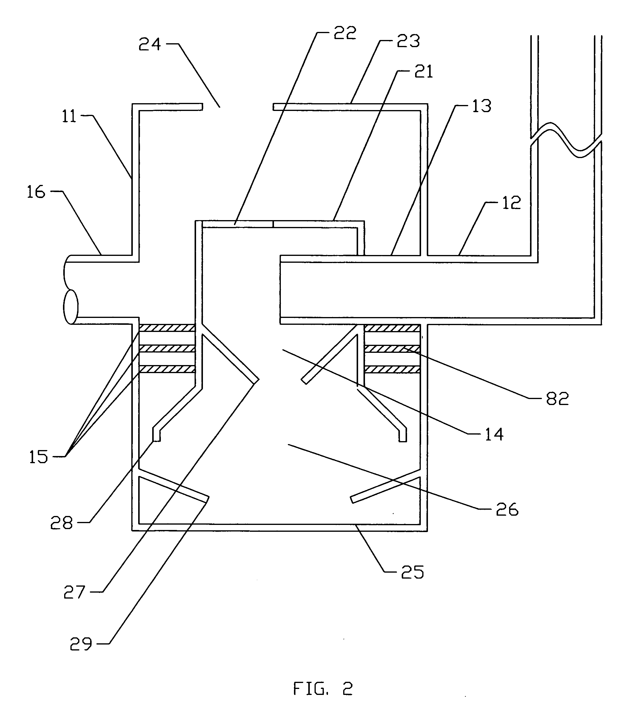
[0026]FIGS. 1, 2, and 3 show the preferred form the invention. FIG. 1 is a plan view of the invention. FIG. 2 is a cross sectional view taken along line A-A as indicated in FIG. 1 and FIG. 3 is a cross sectional view taken along line B-B as indicated in FIG. 1.

[0027] The invention is housed in a container, comprising a floor 25, a top 21 with an opening 22 for access, and side walls 11. A fluid carrying contaminants to be separated is introduced to the system through inlet 12, which penetrates side wall 11 and conveys the fluid to pipe 13. Inlet means 12 conveys a fluid that has sufficient upstream head to force the fluid through the system, as indicated by the vertical section of inlet means 12 in FIG. 2. From pipe 13, the fluid enters vortex chamber 14, tangentially, as commonly done, where the swirling action helps to separate the contaminants from the fluid. Floating contaminants are stored in the vortex chamber 14, trapped by the roof 21 of the vortex chamber. In the roof 21 o...


PUM

PropertyMeasurementUnit
permeableaaaaaaaaaa
permeable barrieraaaaaaaaaa
flow rateaaaaaaaaaa

Abstract

Runoff water from parking lots and filling stations is cleaned by first passing it via an inlet pipe tangentally into a vortex chamber where the swirling action helps to separate the contaminants from the water. Floating contaminants are stored in the vortex chamber, trapped at the top of the chamber by the roof of that chamber and at the lower part of the chamber by a skirt which is part of the chamber and extends downwardly for a limited distance from the inlet pipe. That roof has an access opening to permit removal of the floating contaminants. The body of the fluid thereafter moves downward into a settling chamber where heavier-than-water contaminants settle to the bottom where they can be removed during regular cleaning. As the fluid in the settling chamber builds up it passes through cleaning screens to a clean water outlet. A by-pass overflow pipe to process very large volumes of water extends upward from the settling chamber and ultimately feeds the outlet pipe. Each screen may have louvers projecting from the screen for preventing contaminants from blocking the screen.

Description

RELATED APPLICATION [0001] This application claims the benefit of my copending Provisional application Ser. No. 60 / 514,176, filed Oct. 25, 2003.BACKGROUND OF THE INVENTION [0002] The invention was developed for use in stormwater drainage systems, and combined sewer systems (some older US cities have combined sanitary and stormwater sewers). These sewers are designed and constructed to convey water from a developed area into natural receiving water or other destination. When storm sewers were first constructed, the goal was to remove the water from the developed area and convey it into the receiving water as quickly as possible. At that time, no attention was paid to the potential for pollution from stormwater runoff. [0003] During the last twenty years, stormwater runoff has been identified as a significant source of pollution in waters of the United States. The stormwater runoff from a developed area (a parking lot, for example) can contain oils and other fluids from leaking cars, ...

Claims


Application Information

Patent Timeline
Patent Type & Authority Applications(United States)
IPC IPC(8): B01D17/038B01D21/00B01D21/26
CPCB01D21/0027B01D21/0042B01D21/0087B01D21/265B01D2221/12B01D21/0039B01D21/26
Inventor MEYERMANN, AUSTIN
Owner PANK THOMAS E
Why Eureka
Try Eureka