Modular mini digital video cassette rack

a digital video cassette and module technology, applied in the field of storage racks, can solve the problems of insufficient capacity of the rack, and achieve the effects of minimal disruption, minimal capital investment, and minimal cost per uni

Inactive Publication Date: 2005-04-28
LUKAS PETER
View PDF11 Cites 5 Cited by
  • Summary
  • Abstract
  • Description
  • Claims
  • Application Information

AI Technical Summary

Benefits of technology

[0004] It is an object of this invention to disclose a modular rack system having modular rack units which can readily connect on lateral sides, on top, or on a bottom side portion to another modular unit without disassembly so that the rack system may be expanded with minimal disruption. It is yet a further object of this invention to disclose a modular unit assembly for the modular rack system which comprises a minimal number of non-standard components so that the modular unit assembly can be fabricated with minimal capital and per unit costs. It is yet a another object of this invention to disclose a modular unit assembly which is releasably and lockably connectable to a similar modular unit assembly. The modular unit assembly may be firmly interconnected to another such modular unit without disassembly so that the resulting modular rack system is both rigid and stable.

Problems solved by technology

A rack which initially appears to provide more than sufficient capacity soon becomes inadequate.

Method used


Image

  • Modular mini digital video cassette rack
  • Modular mini digital video cassette rack

Examples


Embodiment Construction

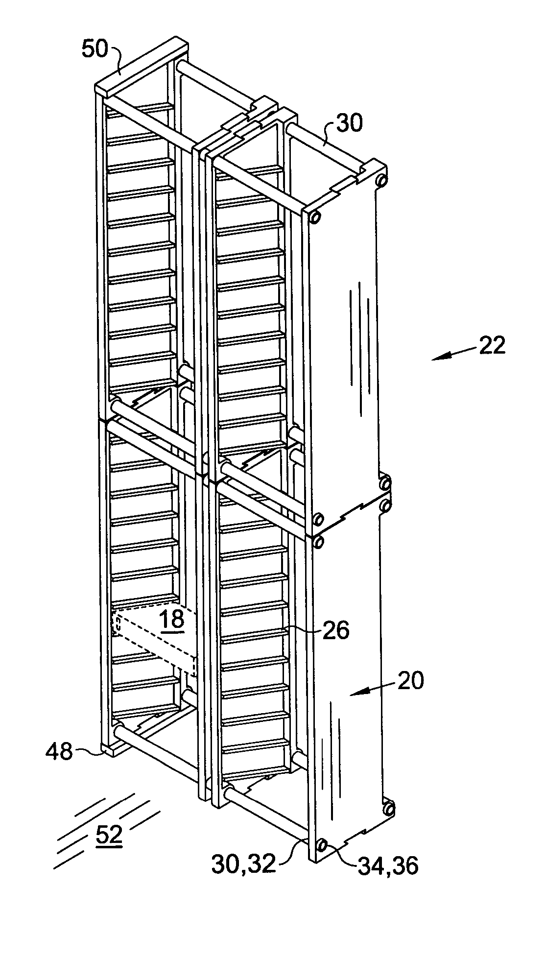
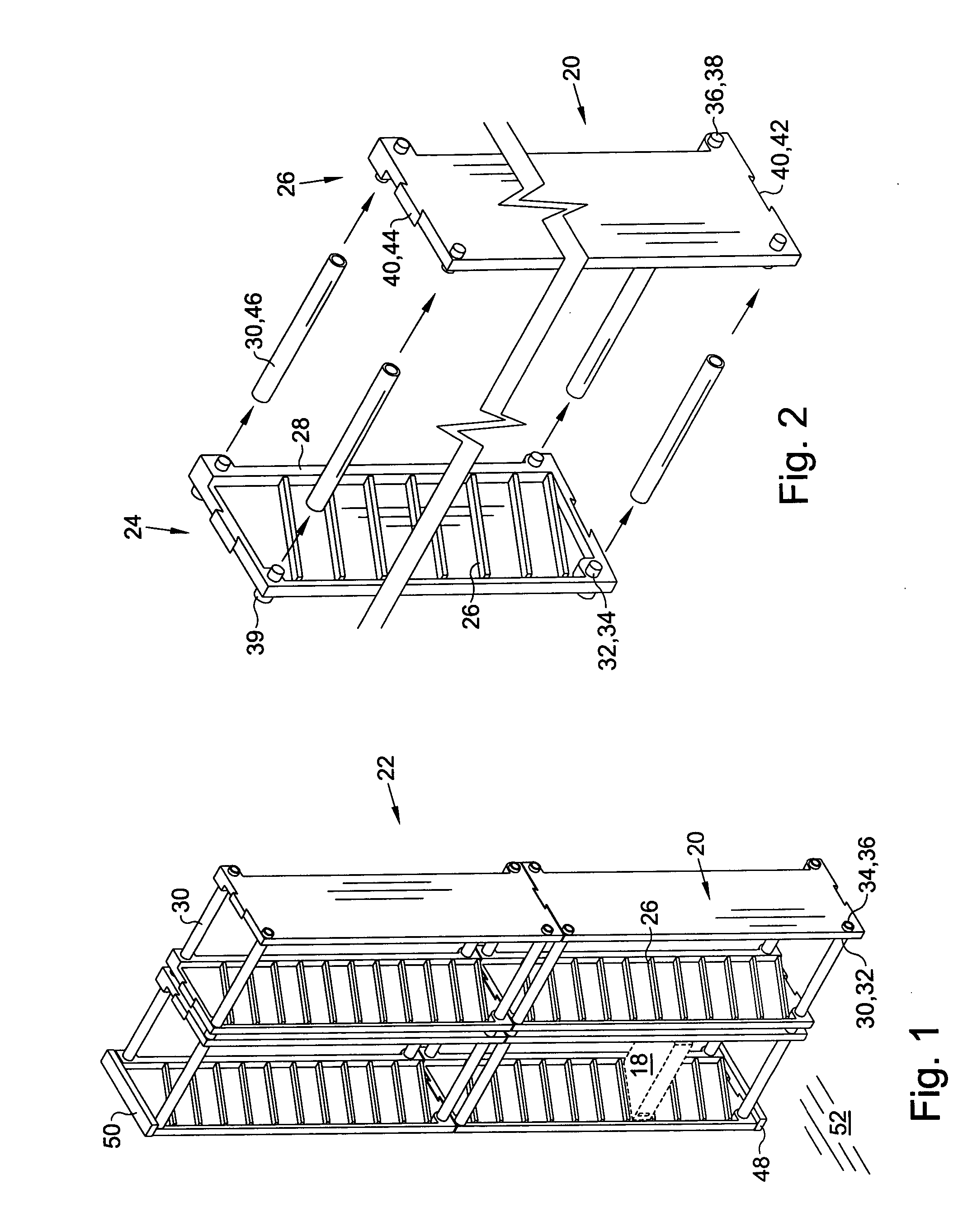
[0011] Turning now to the drawings and more particularly to FIG. 1 we have a perspective view of a modular rack system 22 for holding and organizing cassettes 18. FIG. 2 is a partial exploded perspective view of a modular unit assembly 20 in the modular rack system 22 shown in FIG. 1. The rack system 22 comprises a rack assembly 20 having i) a generally rectangular left side member 24 and right side member 26, each side member 24, 26 having an outer and an inner side portion, a front and rear side portion, and a top and bottom edge portion. Each said inner side portion 24,26 has a plurality of spaced cassette end supports 26, each of which generally extend between the front and rear edge portion of the side members 24,26 and, a rear cassette stop 28 positioned to limit rearward sliding of one of the cassettes 18 along the end support 26. Each inner side portion has upper and lower spacers 30 to space and maintain the left and right side members 24,26 in parallel juxtaposition. The s...


PUM

PropertyMeasurementUnit
dimensionsaaaaaaaaaa
structureaaaaaaaaaa

Abstract

A modular rack for storing and organizing cassettes comprising: a rack assembly having a generally rectangular left and right side member, each side member having an outer and an inner side portion, a front and rear side portion, and a top and bottom edge portion; wherein each said inner side portion has a plurality of spaced cassette end supports, each of which generally extend between the front and rear edge portion of the side member, and, a rear cassette stop positioned to limit rearward sliding of one of the cassettes along the end support; and, wherein each inner side portion has an upper and lower spacer to space and maintain the left and right side portions in parallel juxtaposition and, the spacers extend between spacer attachment means on the side members. The outer side portions of the left and right side members each have a coupling for lateral rack attachment so that assembled rack unit assemblies may be laterally attached to each other. In a preferred aspect of this invention the top and bottom edge portions of the left and right side members have a coupling to interlock top and bottom edge portions so that assembled rack unit assemblies may be vertically attached to each other.

Description

FIELD OF THE INVENTION [0001] This invention relates to storage racks for electronic storage cassettes. More particularly this invention relates to a rack system which comprises vertically and horizontally interlocking modular units. BACKGROUND OF THE INVENTION [0002] There is a need for a rack system to store mini digital (D.V.) video cassettes. Mini D.V. cassettes are used in high end camcorders primarily by professional videographers. It is advantageous to store these cassettes in a rack so that a content label, positioned along a rear edge portion thereon, may be displayed. Such a rack also facilitates individual removal and replacement of a selected cassette. [0003] Individuals typically begin with a few mini D. V. cassettes. Every month or so they acquire more cassettes. A rack which initially appears to provide more than sufficient capacity soon becomes inadequate. Accordingly, a storage and organization rack for the cassettes needs to be expandable. What is needed is a modul...

Claims


Application Information

Patent Timeline
Patent Type & Authority Applications(United States)
IPC IPC(8): A47G29/00G11B23/023G11B33/04
CPCG11B33/0461G11B23/0236
Inventor LUKAS, PETER
Owner LUKAS PETER
Why Eureka
Try Eureka