
Thermal balance temperature control system

a temperature control system and temperature control technology, applied in the field of temperature control systems, can solve the problems of unneeded energy costs, shortening the life of the unit, increasing the maintenance cost of the unit, etc., and achieve the effects of reducing the excess cycling of components, eliminating/reducing undesirable temperature swings in the regulated environment, and eliminating/reducing the utilization of unneeded excess capacity

Inactive Publication Date: 2005-04-28
SIEMENS BUILDING TECHNOLOGIES
View PDF50 Cites 28 Cited by
  • Summary
  • Abstract
  • Description
  • Claims
  • Application Information

AI Technical Summary

Benefits of technology

[0015] As a result, the present invention provides a dynamic real time temperature control system which directly regulates the BTU output of an HVAC package to balance such output with the sensible thermal load being measured in a temperature-regulated enclosure, thereby eliminating / reducing undesirable temperature swings in the regulated environment, reducing excess cycling of components and eliminating / reducing utilization of unneeded excess capacity.

Problems solved by technology

More to the point, those skilled in the art will appreciate that “time cycling” prevents a system from operating in a “real time” mode, and often allows undesirable temperature swings, as well as inefficient operation of the individual components.
This inefficient operation can include the operation of excess cooling / heating capacity (resulting in unneeded energy costs) and excess cycling of the systems components (resulting in the shortening of the life of the unit and / or an increase in maintenance of such unit).
In fact, the prior art has generally believed that real time temperature control systems which attempt to directly regulate BTU output to balance such output with the system load are inherently unstable, and will produce excessive and potentially damaging “short cycling” of the heating / cooling components.
Moreover, the prior art systems are generally inefficient because the supply air is often colder / hotter than necessary to satisfy the measured sensible thermal load.
Finally, such systems are generally incapable of satisfying an unmet cooling / heating load.

Method used


Image

  • Thermal balance temperature control system
  • Thermal balance temperature control system
  • Thermal balance temperature control system

Examples


Embodiment Construction

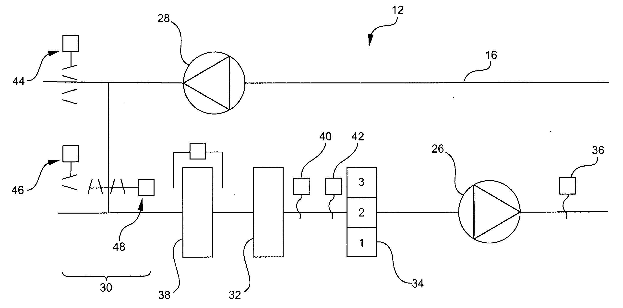
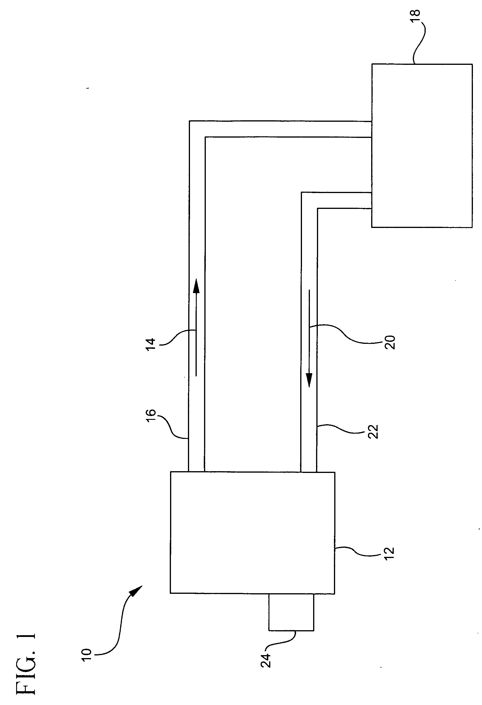
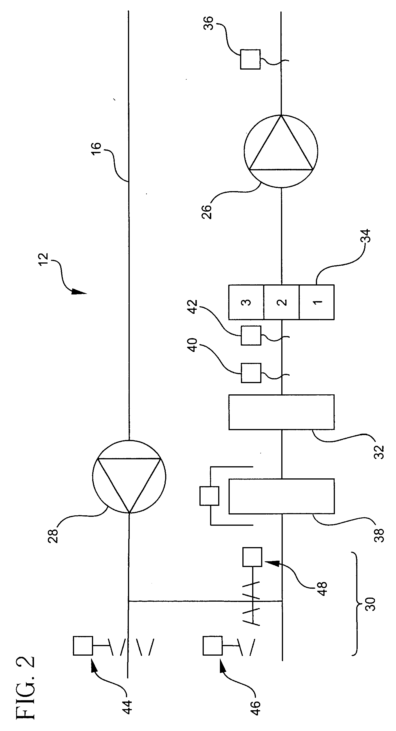
[0022] As discussed more fully hereinbelow, the present invention is directed to a method and apparatus for controlling a temperature-regulated zone utilizing a thermal balance temperature control system. The thermal balance control system is a dynamic real time control system that constantly measures the sensible thermal load in the mentioned zone, and directly regulates the BTU output of the HVAC package to balance such output with the measured sensible thermal load, thus providing a state of system equilibrium. The system will continue to operate in this equilibrium state (without time cycling of any heating / cooling components) until the system measures a change in the sensible thermal load within the mentioned zone.

[0023] The sensible thermal load is the amount of deviation (measured in degrees) between the set point temperature for the zone and the actual zone temperature. When the actual room temperature is above the set point temperature, the sensible thermal load is a cooli...


PUM


Abstract

A method and apparatus for controlling a temperature-regulated zone utilizing a thermal balance temperature control system. The thermal balance control system is a dynamic real time control system that measures the sensible thermal load in the zone, and directly regulates the BTU output of the HVAC package to balance such output with the measured sensible thermal load.

Description

[0001] This application claims the benefit of U.S. Provision Application Ser. No. 60 / 512,410 filed on Oct. 17, 2003.BACKGROUND OF THE INVENTION [0002] The present invention relates to a temperature control system and, more particularly, to a system which directly regulates the system output to balance such output with the sensible thermal load. [0003] Heating, ventilating and air-conditioning (HVAC) systems are used to both heat and cool the air within an enclosure, e.g., a building or zone within such building. An HVAC system typically includes a heating unit, a cooling unit, a supply air fan, a supply duct for directing air into the enclosure, and a return duct for removing air from the enclosure. It will be appreciated by those skilled in the art that HVAC systems are generally designed to operate in one of three modes: a heating mode to heat the enclosure, a cooling mode to cool the enclosure and a economizer mode to ventilate the enclosure. The economizer mode typically utilize...

Claims


Application Information

Patent Timeline
IPC IPC(8): F24F3/044F24F11/00G01K17/04
CPCF24F3/044F24F11/0012Y02B30/767F24F2011/0046F24F11/006F24F11/30F24F2110/10F24F2140/50F24F11/62F24F11/46F24F11/70
Inventor ATTRIDGE, RUSSELL G.
Owner SIEMENS BUILDING TECHNOLOGIES
Learn More