Crystal oscillator

a crystal oscillator and crystal technology, applied in the direction of printed circuit parts, printed circuit casings/cabinets/drawers, printed circuit manufacturing, etc., can solve the problem that metal with printed characters cannot fit in the circuit substrate, and achieve the effect of easy recognition

Inactive Publication Date: 2005-04-28
NIHON DEMPA KOGYO CO LTD
View PDF3 Cites 95 Cited by
  • Summary
  • Abstract
  • Description
  • Claims
  • Application Information

AI Technical Summary

Benefits of technology

[0019] According to the above-mentioned configuration, the groove of the circuit substrate and the projection of the metal cover are provided at one end of each long side, and each long side is unsymmetrical against a center line equally dividing the long side into two. In this case, if the projection of the metal cover is not matched with the groove at one end, the metal with printed characters cannot be fit in the circuit substrate. Thus, by jointing a metal cover with a circuit substrate on which each circuit terminal is regularly disposed, in the reading direction of characters, the crystal oscillator can be correctly mounted on the set substrate.
[0020] Even if characters are printed after jointing the metal cover with the circuit substrate, they can be printed based on one end with a projection and a groove. In this case, the characters are never inverted. Thus, the crystal oscillator can be correctly mounted on the set substrate. Even when a projection and a groove on the short side are provided at one end, the same applies. However, in the case of a small crystal oscillator, it is preferable to provide the projection and groove on the long side since they can be more easily recognized.

Problems solved by technology

In this case, if the projection of the metal cover is not matched with the groove at one end, the metal with printed characters cannot be fit in the circuit substrate.

Method used


Image

  • Crystal oscillator
  • Crystal oscillator
  • Crystal oscillator

Examples


Embodiment Construction

[0027] The preferred embodiment of the present invention is described below with reference to the drawings.

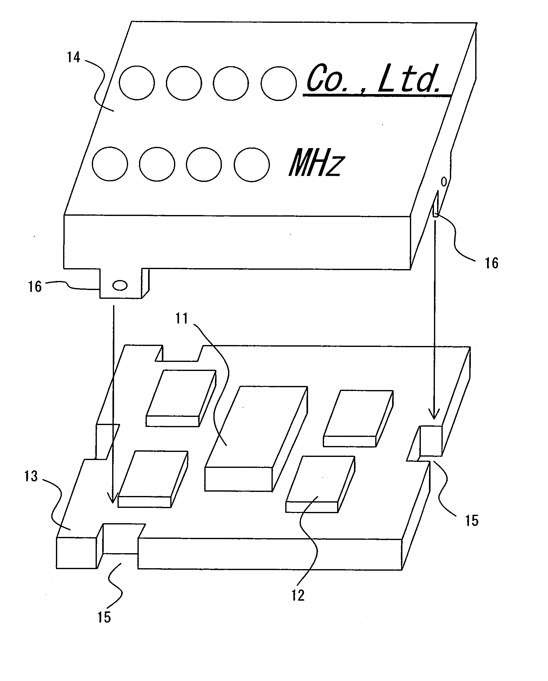
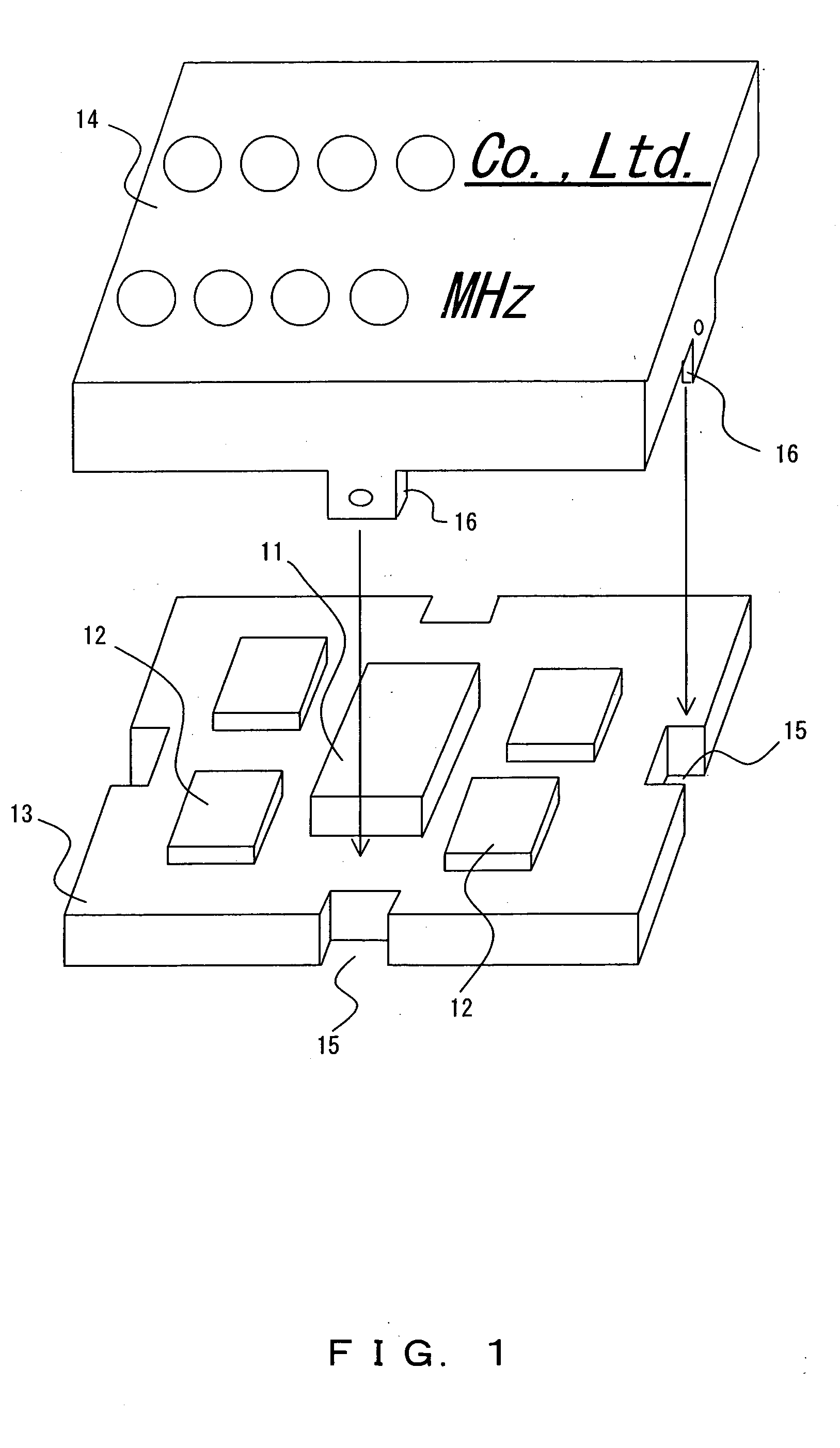
[0028]FIG. 6 is the exploded view of the crystal oscillator in one preferred embodiment of the present invention. The same reference numerals are attached to the same components as those of the prior crystal oscillator shown in FIG. 1 and their descriptions are simplified or omitted. The shape of each groove is not limited to a katakana character “”.

[0029] As described above, the crystal oscillator comprises a circuit substrate 13 on which a crystal vibrator 11, a circuit device 12 and the like are mounted, and its metal cover 14. The circuit substrate 13 is rectangular and has grooves 15 in the shape of a katakana character “1” when viewed from top at the center of each short side and at one end of each long side. The metal cover 14 has projections 16 at the center of each short side and at one end of each long side, corresponding to the grooves 15 of the circuit substrate 1...


PUM


Abstract

A crystal oscillator comprises a rectangular circuit substrate for mounting circuit devices and its metal cover, said circuit substrate has grooves on each long side and on each short side and said metal cover has projections at each aperture end corresponding to the grooves, and which has a swelling from external to internal in each of the projections, wherein both the grooves provided on each short side and the projection of said metal cover are provided at one end of each long side or each short side.

Description

BACKGROUND OF THE INVENTION [0001] 1. Field of the Invention [0002] The present invention relates to a crystal oscillator and more particularly to a circuit substrate on which a crystal vibrator and circuit devices are mounted, and its cover. [0003] 2. Description of the Related Art [0004] A crystal oscillator is built in a variety of electronic devices, as the reference source of frequency or time. Such a crystal oscillator includes, for example, a PLL (phase-locked loop) voltage control oscillator usually composed of discrete components. [0005]FIG. 1 is the exploded view of one conventional crystal oscillator. [0006] The crystal oscillator comprises a circuit substrate 13 on which a crystal vibrator 11 composing a voltage control oscillator, and circuit devices 12, such as a voltage variable capacitor device and the like, and its metal cover 14. The circuit substrate 13 is made of glass epoxy and is rectangular with a long side and a short side. The circuit substrate 13 also has g...

Claims


Application Information

Patent Timeline
Patent Type & Authority Applications(United States)
IPC IPC(8): H03B5/32H05K3/34
CPCH03B5/32H05K3/3405H05K2201/09181H05K2203/168H05K2201/10371H05K2203/167H05K2201/09936
Inventor MATSUMOTO, TAKASHI
Owner NIHON DEMPA KOGYO CO LTD
Why Eureka
Try Eureka