Tamper sensing method and apparatus

a technology of tampering and sensing devices, applied in the field of security systems, can solve problems such as making devices and their stored data useless, and achieve the effect of reducing the cost of monitoring and controlling the devi

Active Publication Date: 2005-04-28
LENOVO GLOBAL TECH INT LTD
View PDF7 Cites 15 Cited by
  • Summary
  • Abstract
  • Description
  • Claims
  • Application Information

AI Technical Summary

Benefits of technology

[0007] As shown and described, the screw or bolt which interconnects the two device enclosure portions is electrically connected to the device printed circuit board by passing through an opening in the board and engaging a connector element soldered to the board. This connector element is formed as a flat annular member with flexi...

Problems solved by technology

This response may be erasure of the memory or mechanical ...

Method used


Image

  • Tamper sensing method and apparatus
  • Tamper sensing method and apparatus
  • Tamper sensing method and apparatus

Examples


Embodiment Construction

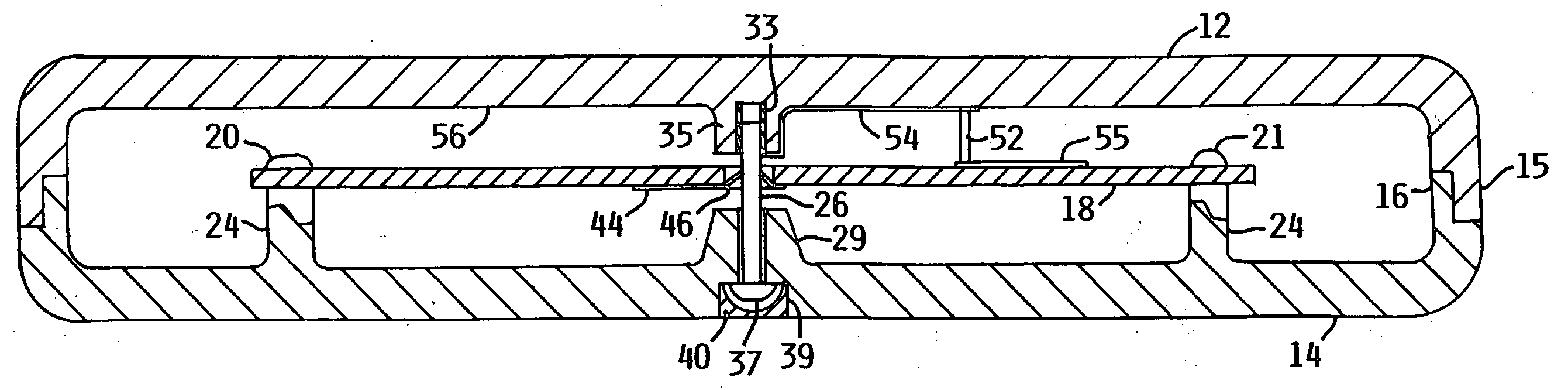
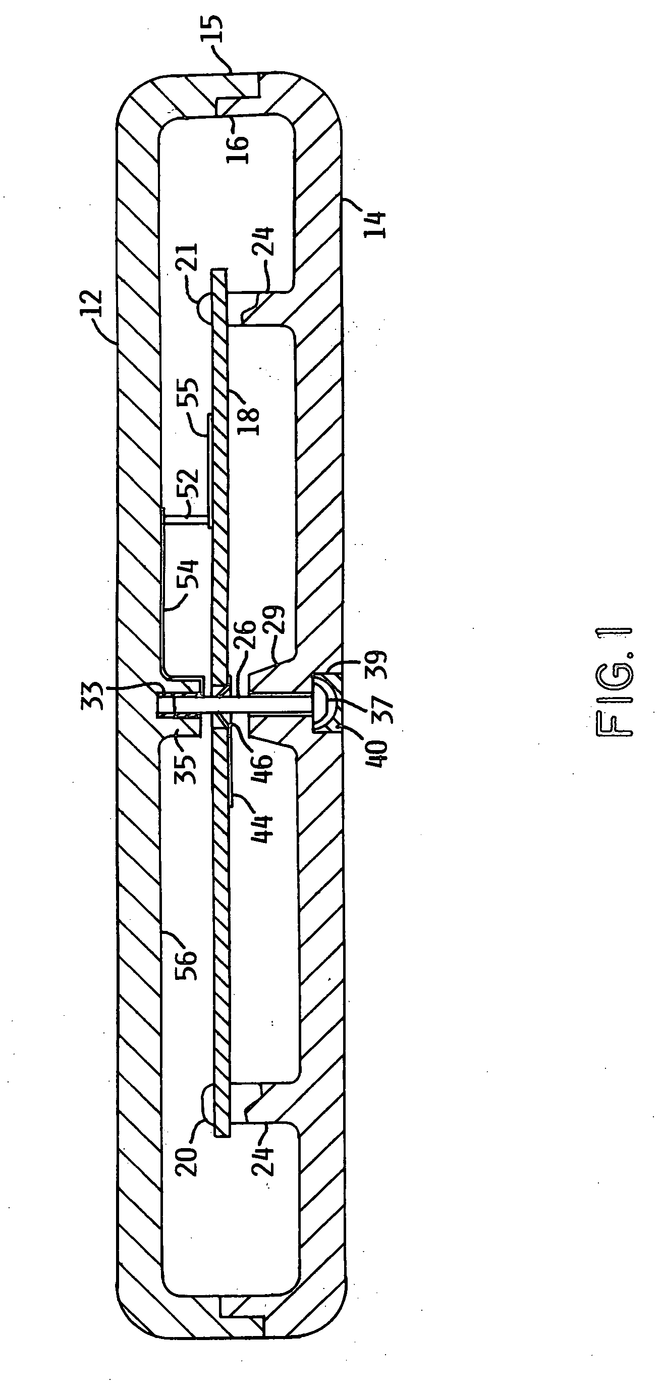
[0012]FIG. 1 illustrates an electronic device contained within a housing having an upper enclosure member 12 and a lower enclosure member 14 with respective marginal flanges 15 and 16 which align and position the enclosure members in the assembled condition. A printed circuit board 18 is mounted on the lower enclosure member 14 by screws 20 and 21 which extend through holes in the printed circuit board and are received in axial openings in bosses 24 that are formed as an integral part of the lower enclosure member 14.

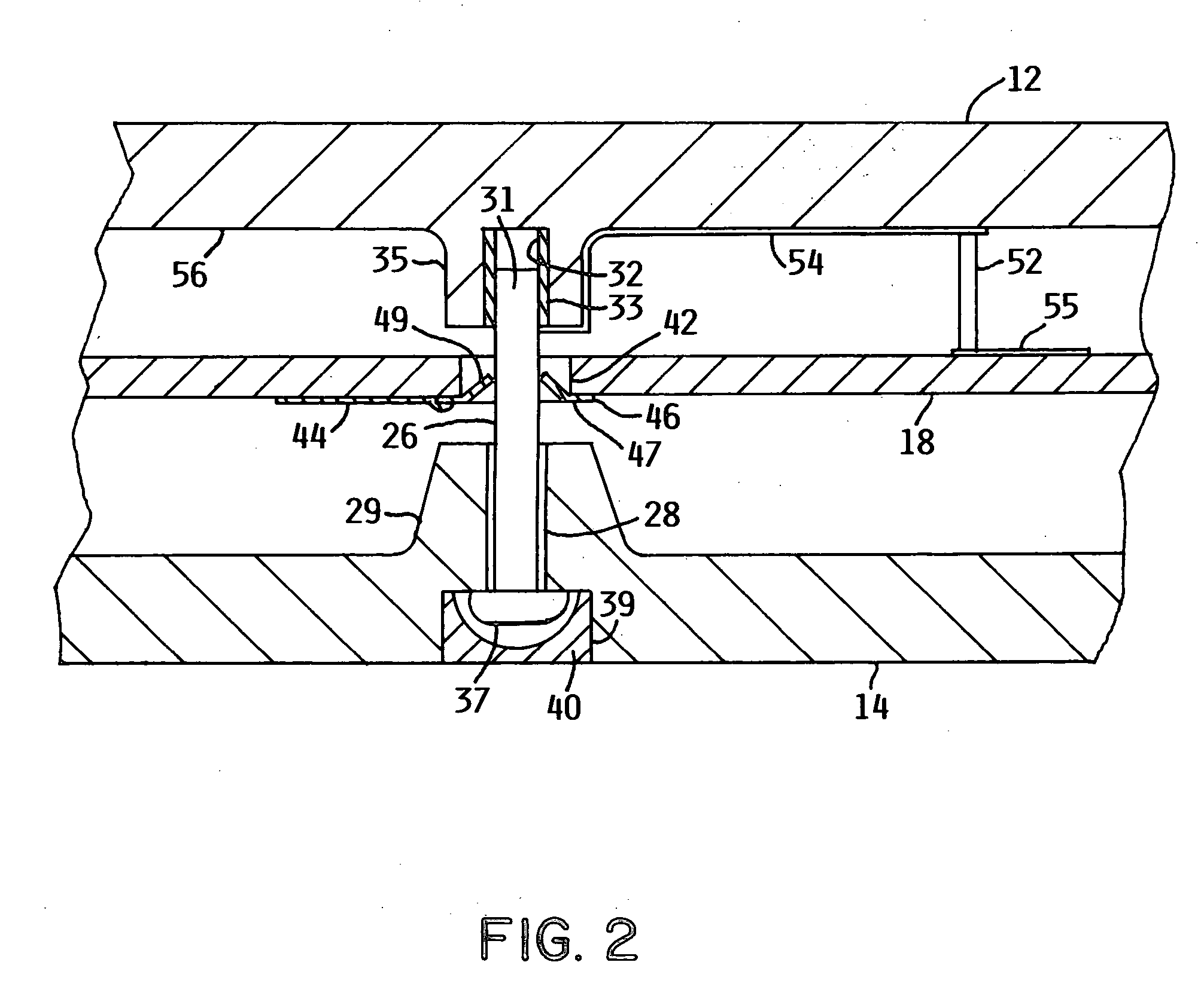
[0013]FIG. 2 shows an enlarged central portion of the device shown in FIG. 1. The enclosure members 12 and 14 are secured together by a screw 26 which extends through a cylindrical opening 28 in the boss or raised portion 29, formed as an integral portion of the lower enclosure member 14 with the terminal end 31 received in a threaded opening 32 in the upper enclosure member 12. The threaded opening in enclosure member 12 is formed in a cylindrical metal insert 33 that...


PUM


Abstract

A tamper sensing circuit is provided for an electrical device wherein an enclosure may be opened to access data by a user that does not possess the ability to achieve normal access by satisfying data security measures such as use of a password. A screw used to secure enclosure halves together is connected by a conductive coating at the enclosure member surface into which the screw is threaded to connect a tamper sensing circuit to the device ground potential. A tamper sensing circuit output node is maintained at the circuit ground potential as long as the screw is in electrical contact with the enclosure conductive coating. When the screw is disengaged from the enclosure member threaded opening, the output node is no longer grounded and rises to a supplied electrical potential indicating tampering and enabling appropriate corrective action. The conductive coating on the enclosure member which connects the screw to circuit ground may be applied or may already be present to suppress electromagnetic interference.

Description

FIELD OF THE INVENTION [0001] The present invention pertains to security systems and more particularly to the sensing of tampering with respect to devices housed within enclosure members secured together by a connector such as a screw or bolt. BACKGROUND OF THE INVENTION [0002] The design of data handling devices that may be used for the storage of confidential data will normally require the inclusion of means to detect tampering or the unauthorized disassembly of the device that could be initiated to access the stored confidential data. The smaller the device, the greater the likelihood that it will be lost, mislaid, subject to theft or otherwise be beyond the custody and control of the user and owner of the stored data. In such circumstances, with the device in the possession and control of a party unable to use a password or comply with other requirements to achieve normal access to the stored data, tampering may occur by opening the housing in an attempt to use other extraordina...

Claims


Application Information

Patent Timeline
IPC IPC(8): G08B13/14
CPCG08B13/126G08B13/149G08B13/1463
Inventor ALLEN, JONATHAN MICHAELBUTTERBAUGH, MATTHEW ALLEN
Owner LENOVO GLOBAL TECH INT LTD
Why Eureka
Try Eureka