System and method for multiple antennas having a single core

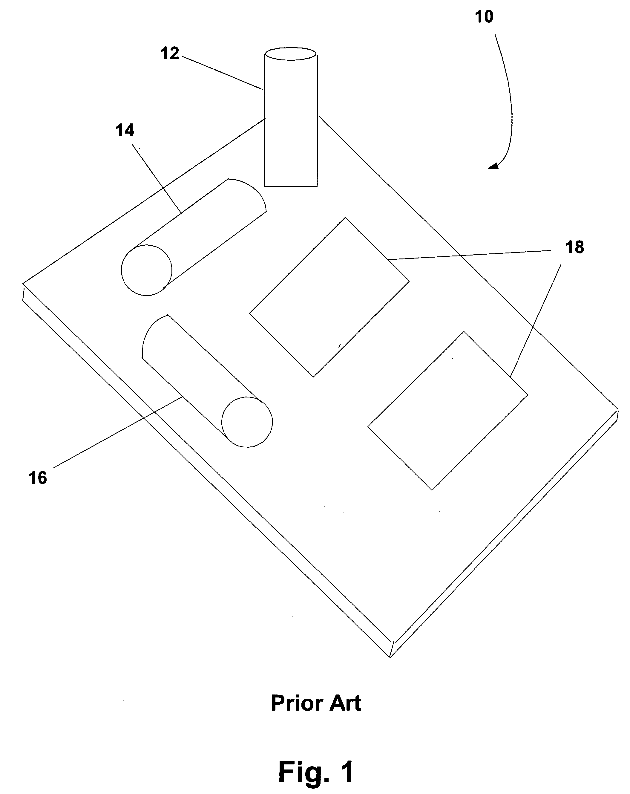
a technology of multiple antennas and cores, applied in the field of system and method for multiple antennas having a single core, can solve the problems of increasing the space required for the system, inducibly coupled implant units, and not giving patients complete freedom from external monitoring or control devices

Inactive Publication Date: 2005-04-28
MEDTRONIC MIMIMED INC
View PDF10 Cites 44 Cited by
  • Summary
  • Abstract
  • Description
  • Claims
  • Application Information

AI Technical Summary

Benefits of technology

[0014] The activation circuitry may include a multiplexer for facilitating separate activation of the first winding, the second winding or the third winding. The first winding, the second winding and the third winding may transmit or receive a radio frequency signal. The direction of the first magnetic field may be orthogonal to the direction of the second magnetic field and the direction of the third magnetic field may be orthogonal to the direction of the first magnetic field and the second magnetic field.

Problems solved by technology

Inductively coupled implant units to date, however, have not given patients complete freedom from external monitoring or control devices.
This type of configuration greatly increases the space required to house the system.
Since space in an implantable unit is critical and always at a premium, the space required by this type of three-antenna system is relatively large and, thus, is a drawback for patients who are outfitted with an implant unit utilizing this type of system.
Systems of this type have mobility limitations, rendering the patient stationary while trying to transmit or receive data.
In addition, because of the directional nature of the a single antenna device, and the inability of the patient to ascertain the exact orientation of the implanted antenna, maximum data transfer rates and accuracy may be diminished in a single antenna system.

Method used


Image

  • System and method for multiple antennas having a single core
  • System and method for multiple antennas having a single core
  • System and method for multiple antennas having a single core

Examples


Embodiment Construction

[0027] In the following description of preferred embodiments, reference is made to the accompanying drawings which form a part hereof, and in which are shown by way of illustration specific embodiments in which the invention may be practiced. It is to be understood that other embodiments may be utilized and structural changes may be made without departing from the scope of the preferred embodiments of the present invention.

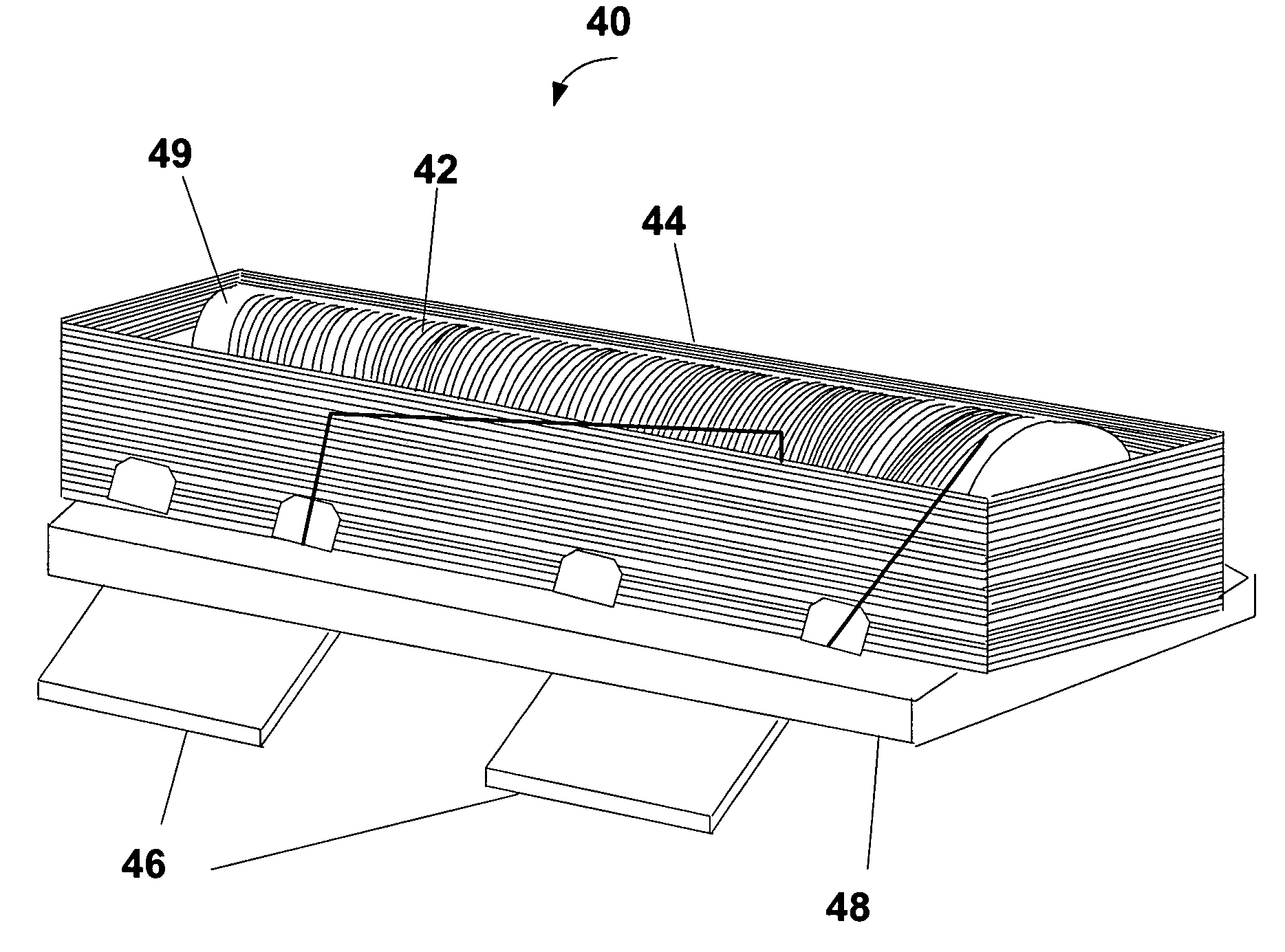
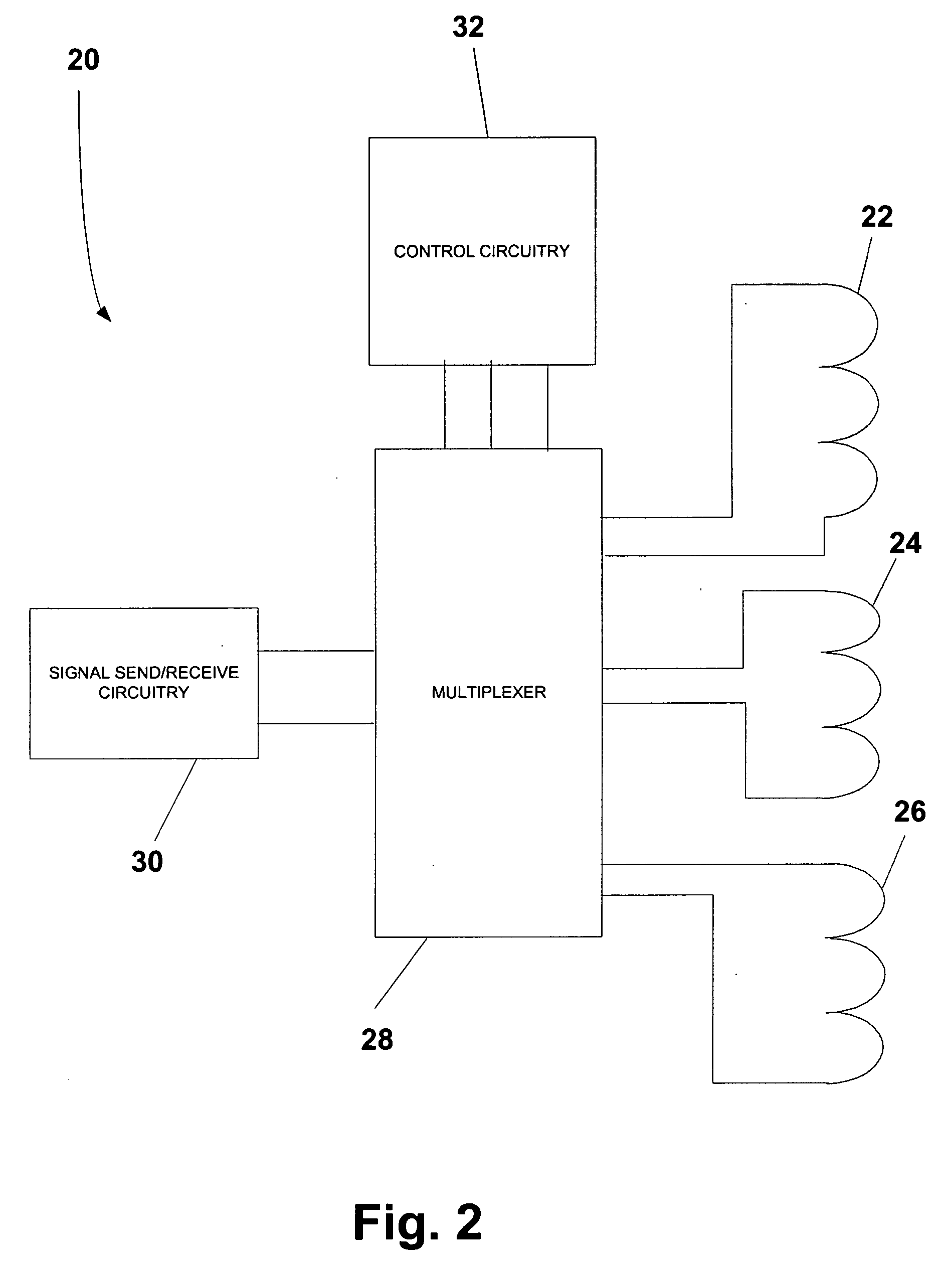
[0028] Although the following description is directed primarily toward methods and systems for inductively coupling an implant unit to an external device via multiple antennas having a single core, embodiments of the present invention may be used in a variety of capacities and applications. For example, embodiments of the present invention may be used to couple one external device to another external device or to couple one internal device to another internal device. Generally, embodiments of the present invention may be adapted for use in any type of system wher...


PUM

PropertyMeasurementUnit
timeaaaaaaaaaa
frequenciesaaaaaaaaaa
distancesaaaaaaaaaa

Abstract

A system and method for multiple antennas on a single core. The system may include a first core, a first winding wound about the first core for transmitting / receiving electromagnetic signals, and a second winding for transmitting / receiving electromagnetic signals wound about the first core and the first winding. The first winding and the second winding may be wound such that a direction of a first magnetic field generated by the first winding is different than a direction of a second magnetic field generated by the second winding. The system may also include activation circuitry connected to the first winding and the second winding. The activation circuitry may activate the first winding separately from the second winding. The system may be expanded to three or more coils / antennas disposed on a single core.

Description

BACKGROUND [0001] 1. Field of the Invention [0002] The present invention relates to systems and methods for providing a plurality of antennas using a single core and, in particular embodiments, to systems and methods for providing an implantable device having multiple antennas and a single core that is inductively coupled to an external unit. [0003] 2. Description of Related Art [0004] The ability to inductively couple radio signals between two or more coils has greatly facilitated the use of implantable devices in patients who require internal monitoring, sensing or regulation of various physical parameters or who require internal delivery of a drug or medication. RF communication between an implant unit and an external device has allowed many such patients to receive effective medical treatment and / or analysis while maintaining mobility realizing the mobility and other benefits of an implanted device. [0005] For example, for patients requiring automatic pacing of the heart, implan...

Claims


Application Information

Patent Timeline
Patent Type & Authority Applications(United States)
IPC IPC(8): A61N1/372H01Q7/08H01Q21/24
CPCA61N1/37223A61N1/37229Y10T29/49016H01Q21/24H01Q7/08
Inventor HESS, PHILLIP B.MORGAN, WAYNE A.
Owner MEDTRONIC MIMIMED INC
Why Eureka
Try Eureka