Broadband tunable antenna and transceiver systems

a transceiver and antenna technology, applied in the direction of radiating element structural forms, elongated active element feeds, resonance antennas, etc., can solve the problems of difficult to achieve extended frequency ranges with a single system, and the general need for extended range systems are not generally satisfied

Inactive Publication Date: 2005-04-28
SENSOR SYST
View PDF17 Cites 22 Cited by
  • Summary
  • Abstract
  • Description
  • Claims
  • Application Information

AI Technical Summary

Problems solved by technology

Although some conventional transceiver systems have operated across restricted frequency ranges, they do not generally satisfy the need for systems that have an extended range (e.g., from 30 MHz to upper limits in the ...

Method used


Image

  • Broadband tunable antenna and transceiver systems
  • Broadband tunable antenna and transceiver systems
  • Broadband tunable antenna and transceiver systems

Examples


Embodiment Construction

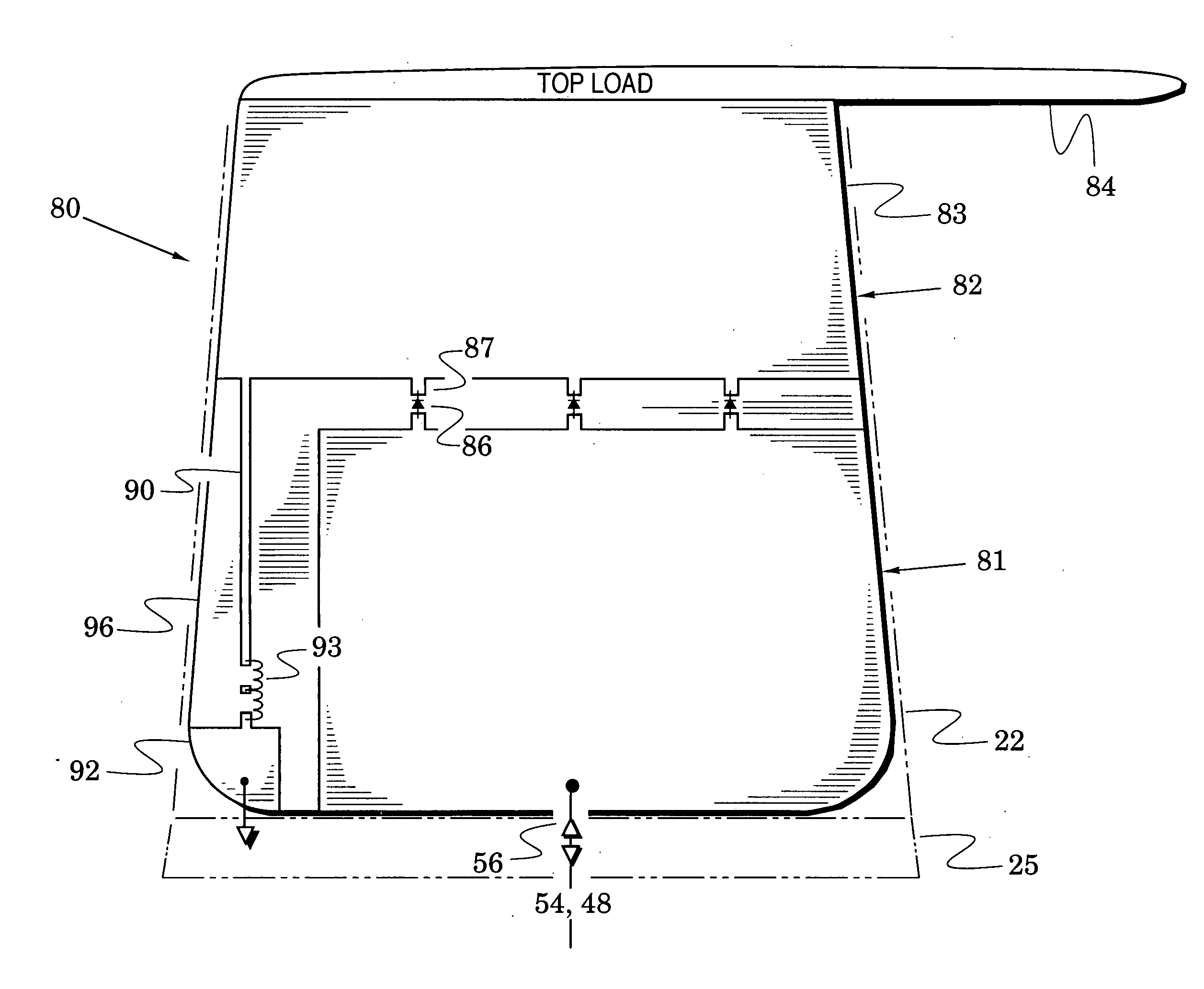
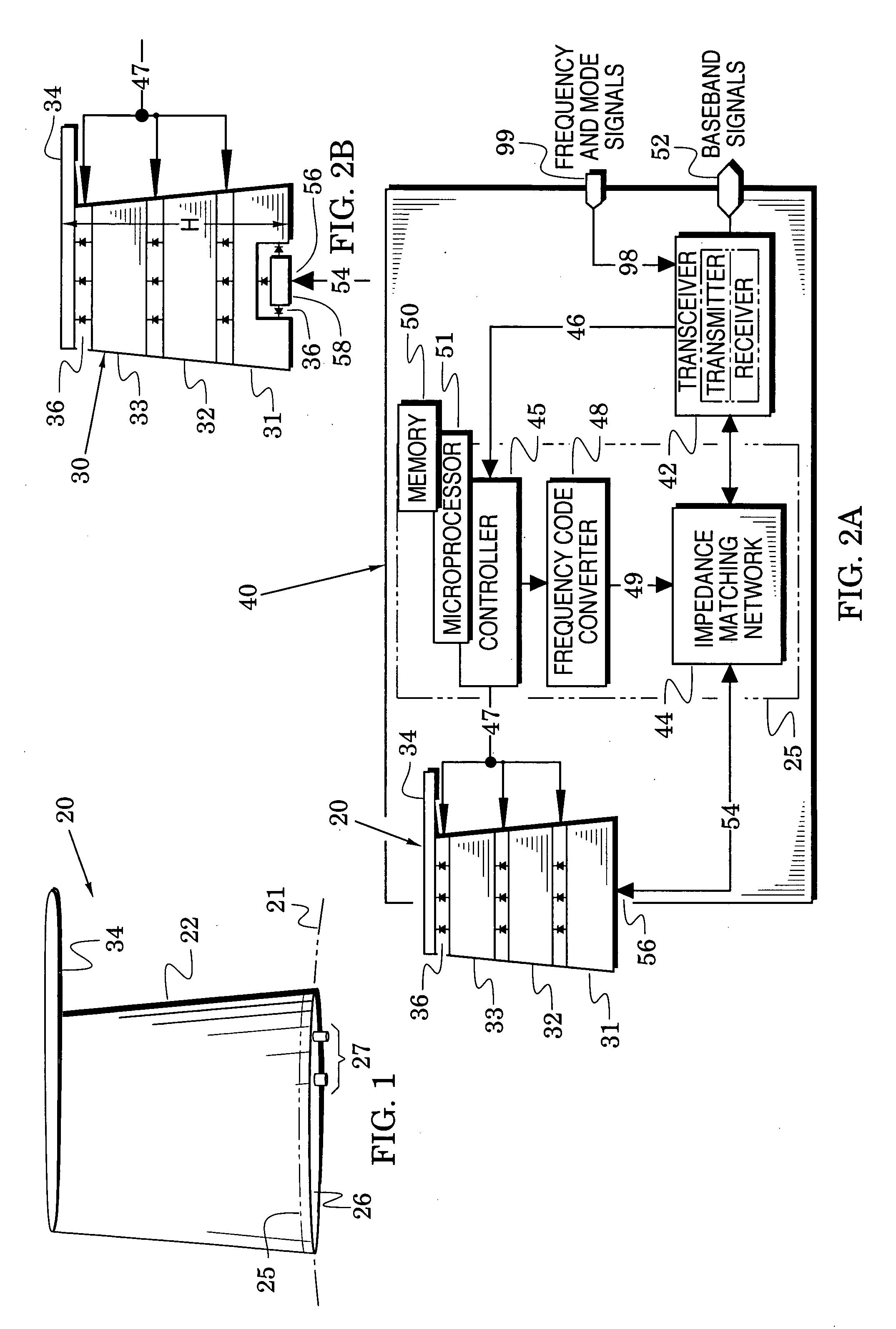
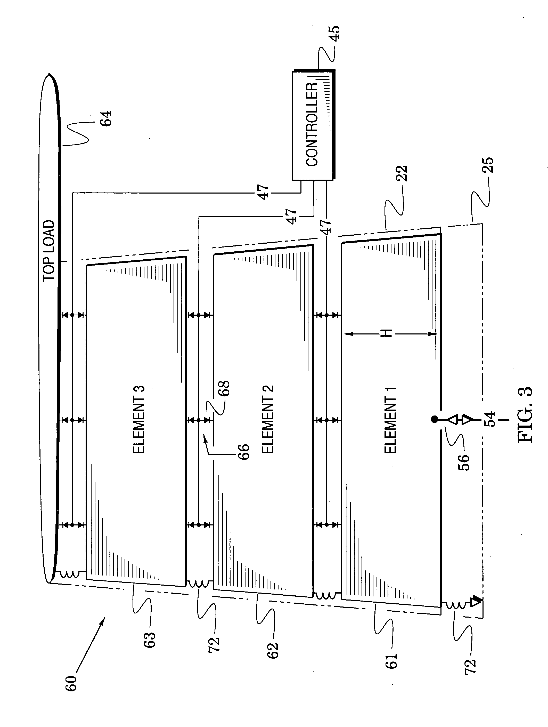
[0016]FIGS. 1-4 illustrate multi-element antennas and transceiver systems that include the antennas. The antennas provide a significantly-enhanced degree of freedom (i.e., number of options) for improving the operational parameters of the systems as they are tuned across a wide operational band. The features and advantages of these antennas and systems will become apparent in the following description.

[0017] In particular, a multi-element antenna embodiment 20 of the present invention is shown in FIG. 1 and FIG. 2A is a block diagram of a transceiver system embodiment 40 of the invention that mates the antenna to a transceiver 42. The transceiver system 40 includes an impedance matching network 44 coupled between the antenna 20 and the transceiver 42 and a controller 45 which receives frequency and mode commands 46 from the transceiver.

[0018] The controller 45 converts these commands to switch command signals 47 for the antenna 20 and to frequency codes for a frequency code conver...


PUM


Abstract

The present invention is directed to multi-element antennas that include, for each adjacent pair of antenna elements, at least one switch arranged to selectively connect that pair to thereby selectively alter an antenna dimension. Accordingly, a multi-element antenna can be configured to enhance its gain at different operational frequencies while a corresponding impedance matching network can enhance the impedance match (i.e., reduce reflected signal energy) between the antenna and a corresponding system (e.g., a transceiver system). The antenna and system can thus be effectively tuned across a wide operational band. The antenna and impedance matching network are configured with switch command signals and match command signals that are provided in response to each of a plurality of frequency codes.

Description

CROSS REFERENCES TO RELATED APPLICATIONS [0001] This application claims the benefit of U.S. Provisional Application Ser. No. 60 / 508,419 filed Oct. 3, 2003.BACKGROUND OF THE INVENTION [0002] 1. Field of the invention [0003] The present invention relates generally to antenna and transceiver systems and, more particularly, to systems that are directed to aircraft installations. [0004] 2. Description of the Related Art [0005] There exists a substantial demand for antenna and transceiver systems that can rapidly hop between channels that are distributed over wide frequency bands for the purpose of communicating a variety of communication signals (e.g., voice, data, imagery and video). Although some conventional transceiver systems have operated across restricted frequency ranges, they do not generally satisfy the need for systems that have an extended range (e.g., from 30 MHz to upper limits in the 1 to 2 GHz range). Such extended frequency ranges have been difficult to achieve with a si...

Claims


Application Information

Patent Timeline
IPC IPC(8): H01QH01Q3/24
CPCH01Q1/28H01Q9/145H01Q9/42H01Q9/40H01Q9/36
Inventor LIN, ZHEN BIAOLIN, JIAN QUANROBIN, SEYMOUR
Owner SENSOR SYST
Why Eureka
Try Eureka