Frequency tunable resonant scanner

a frequency tunable resonant and scanner technology, applied in the field of optical scanners, can solve problems such as the difficulty of manufacturing actuators having a predetermined natural frequency

Inactive Publication Date: 2005-04-28
SAMSUNG ELECTRONICS CO LTD
View PDF6 Cites 14 Cited by
  • Summary
  • Abstract
  • Description
  • Claims
  • Application Information

AI Technical Summary

Benefits of technology

[0009] To solve the above and / or other problems, the present invention provides an optical scanner in which a tuning electrode is installed in an area corresponding to a stage so that a frequency of the stage can be controlled during a driving of the optical scanner.

Problems solved by technology

However, when an MEMS structure is accurately manufactured, it is very difficult to manufacture an actuator having a predetermined natural frequency due to a deviation in process.

Method used


Image

  • Frequency tunable resonant scanner
  • Frequency tunable resonant scanner
  • Frequency tunable resonant scanner

Examples


first embodiment

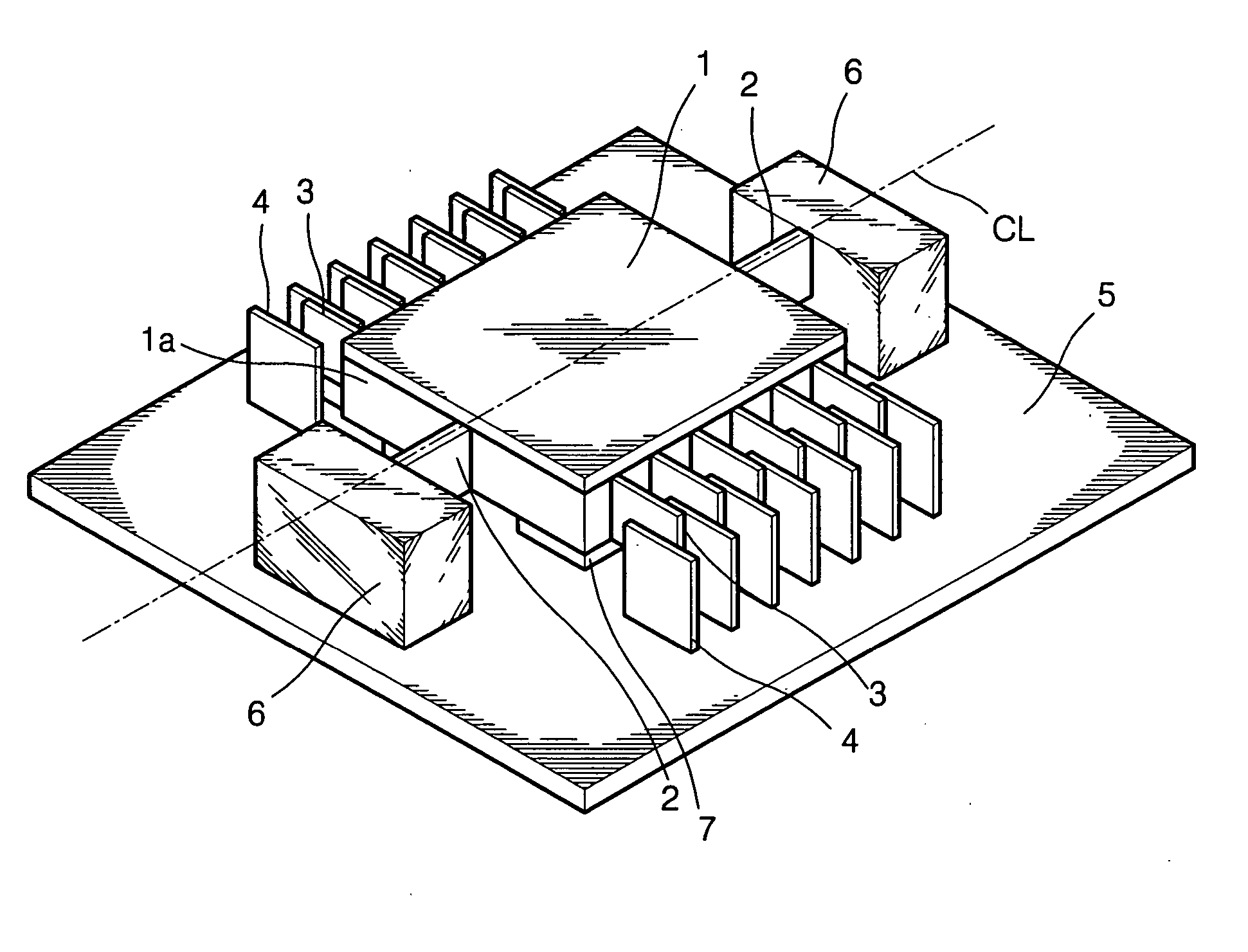
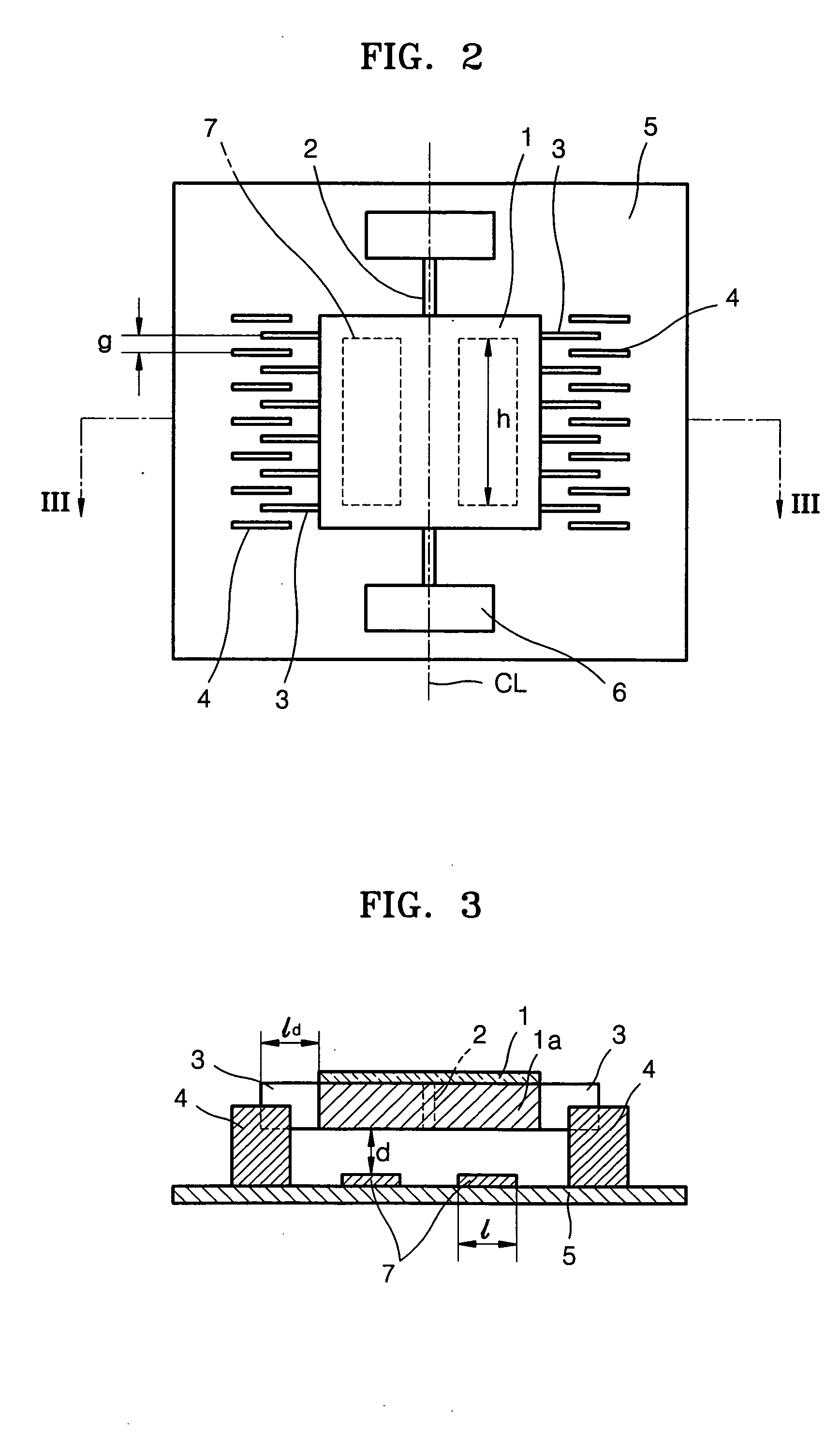
[0034] Referring to FIGS. 1 through 4, in an optical scanner according to the present invention, a stage 1a is suspended by a support portion supporting both side ends of the stage 1a above a substrate 5 made of Pyrex glass. The support portion includes a torsion spring 2 connected to a middle portion of either side edge of the stage 1a and supporting a seesaw motion of the stage 1a, and an anchor 6 supporting the torsion spring 2 to be suspended on the substrate 5.

[0035] A mirror surface 1 which is an optical scanning surface is formed on an upper surface of the stage 1a. A plurality of driving comb electrodes 3 are formed at both sides of the stage 1a to have a predetermined length and parallel to one another.

[0036] A plurality of fixed comb electrodes 4 disposed to alternate with the driving comb electrodes 3 are formed on an upper surface of the substrate 5 to have a predetermined height and parallel to one another. The driving comb electrodes 3 formed on a lower surface of the...

third embodiment

[0062]FIG. 9 is a sectional view of an optical scanner according to the present invention. The same reference numerals are used for the same constituent elements described in the previous embodiments and detailed descriptions thereof will be omitted herein.

[0063] Referring to FIG. 9, the structure of the scanner according to the third embodiment is similar to the scanner according to the first embodiment. However, electrodes 8 and 9 for the frequency tuning of the scanner are vertically formed on the lower portion of the stage 1a and the upper portion of the substrate 5. The driving comb electrode for tuning 9 on the lower portion of the stage 1a and the fixed comb electrode for tuning 8 on the upper portion of the substrate 5 are installed to alternate with one another. When a tuning voltage is applied to the fixed comb electrode for tuning 8 during the driving of the stage 1a, a tuning force is generated between the driving comb electrode 9 and the fixed comb electrode for tuning ...

fifth embodiment

[0068] Referring to FIG. 12, in the scanner the fixed comb electrodes 14 to drive the stage 1a are horizontally fixed to the anchor portion 10 fixed on the substrate 5. The electrodes for tuning the resonant frequency of the scanner are vertically formed on the lower portion of the stage 1a and the upper portion of the substrate 5. The driving comb electrodes 9 for tuning on the lower portion of the stage 1a and the fixed comb electrode for tuning 8 are installed to be alternate with one another. When a tuning voltage is applied to the fixed comb electrodes for tuning 8 during the driving of the stage 1a, a tuning force is generated between the driving comb electrodes 9 for tuning and the fixed comb electrodes for tuning 8. Accordingly, the constant of the torsion spring 2 changes so that the driving frequency decreases. Thus, the resonant frequency of the scanner can be controlled by adjusting the tuning voltage.


PUM


Abstract

Provided is a one-axis driving optical scanner which includes a substrate, a stage separated from the substrate to a predetermined height and having an upper surface where an optical scanning surface is formed, a torsion spring supporting the stage from middle portions of both edge sides of the stage, a support portion fixed to the substrate to support the torsion spring, a driving portion rotating the stage with respect to the torsion spring forming a center axis, and a flat panel type tuning electrode arranged in an area of the substrate corresponding to the stage.

Description

BACKGROUND OF THE INVENTION [0001] This application claims the priority of Korean Patent Application No. 2003-74662, filed on Oct. 24, 2003, in the Korean Intellectual Property Office, the disclosure of which is incorporated herein in its entirety by reference. [0002] 1. Field of the Invention [0003] The present invention relates to an optical scanner having an MEMS (micro electromechanical system) structure in which a frequency is tunable, and more particularly, to an optical scanner in which a resonant frequency is tunable by using a tuning electrode. [0004] 2. Description of the Related Art [0005] Microactuators are used as scanners to deflect a laser beam in projection TVs. U.S. Patent Publication Application No. 2003-39089 discloses an example of an MEMS type scanner. [0006] In an optical scanner disclosed in U.S. Patent Publication Application No. 2003-39089, a stage seesaws with respect to a torsion spring supporting the stage as a center shaft. As the stage is seesawing, lig...

Claims


Application Information

Patent Timeline
Patent Type & Authority Applications(United States)
IPC IPC(8): B81B3/00G02B26/08G02B26/10
CPCG02B26/0841G02B26/08
Inventor KO, YOUNG-CHULLEE, JIN-HOLEE, JU-HYUNMUN, YONG-KWEUN
Owner SAMSUNG ELECTRONICS CO LTD
Why Eureka
Try Eureka