Beam pump dynamic load monitoring and methods

a beam pump and dynamic load technology, applied in the field of pumping systems, can solve the problems of affecting the small signal, the temperature sensitivity of the materials to which the device is attached,

Inactive Publication Date: 2005-04-28
PCS FERGUSON
View PDF12 Cites 19 Cited by
  • Summary
  • Abstract
  • Description
  • Claims
  • Application Information

AI Technical Summary

Problems solved by technology

A difficulty with these measurement techniques is the temperature sensitivity of the materials to which the device is attached and how this affects the small signal measured by a strain gauge.

Method used


Image

  • Beam pump dynamic load monitoring and methods
  • Beam pump dynamic load monitoring and methods
  • Beam pump dynamic load monitoring and methods

Examples


Embodiment Construction

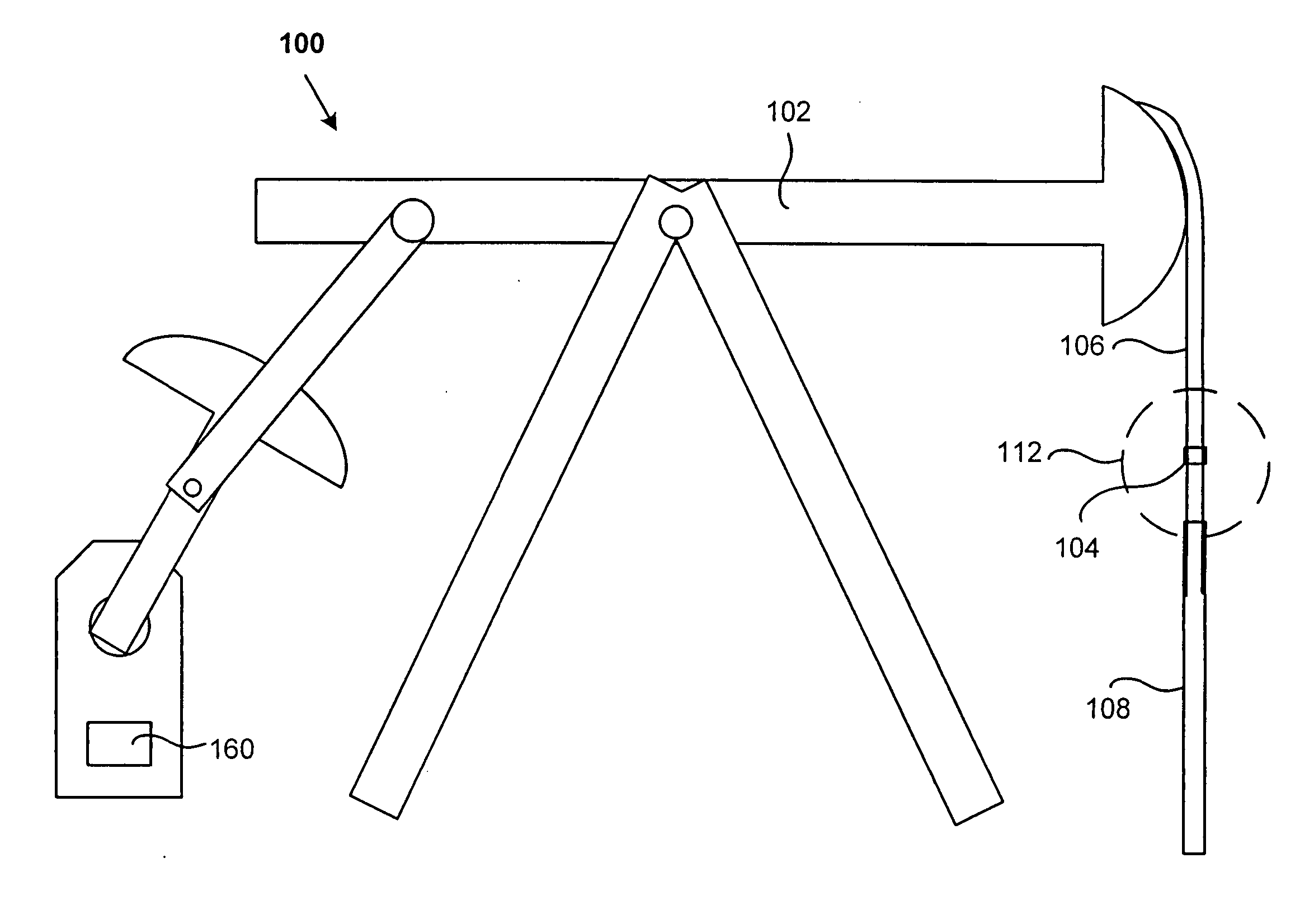
[0013] According to embodiments of the present invention, a beam pump dynamic loading monitoring device is attached to a cable harness of the device. In some embodiments, the device is attached to two cables of the harness; in other embodiment it is attached to only one cable. Herein, “two cables” will be understood to include “two different portions of the same cable.” Some embodiments of the monitoring device are attached noninvasively and without the need for a separate power supply. The device also may be attached at a point on the pump where temperature changes do not alter measurements. Embodiments of the device include power supplies, such as solar cells and / or batteries. Some embodiments also include wireless transmitters so that the device may be installed in the field and monitored remotely.

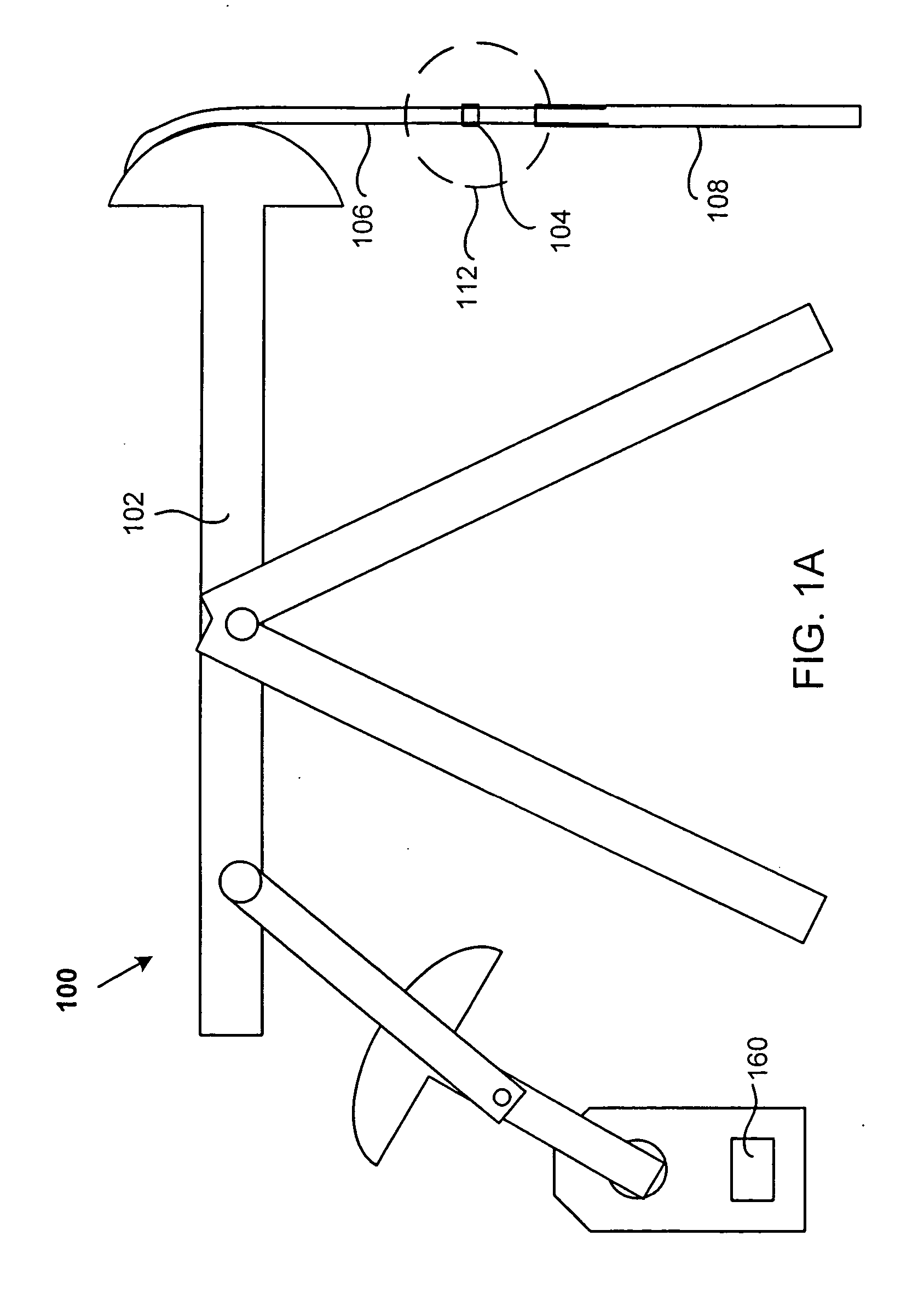
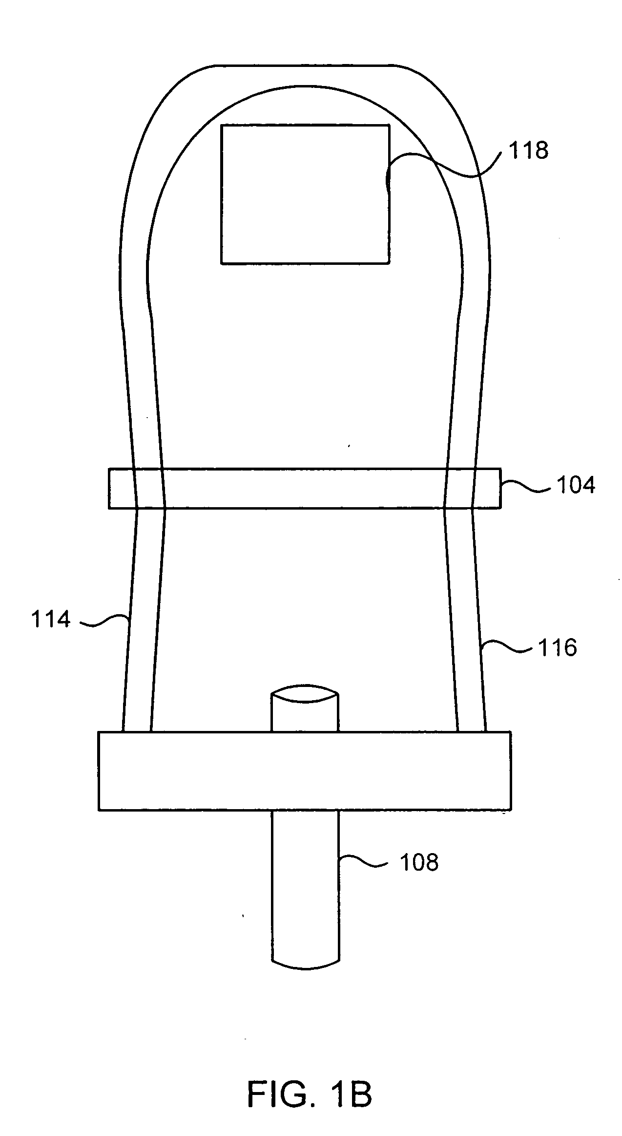
[0014] Having described embodiments of the present invention generally, attention is directed to FIGS. 1A to 1C, which illustrate a specific example of a beam pump system 100 according...


PUM


Abstract

A pump monitoring system includes a monitoring device configured for attachment to a cable harness of a pump, a strain gauge configured to measure dynamic loading of at least one cable of the cable harness as the pump operates, a wireless transmitter configured to transmit the dynamic loading measurement, and an external device configured to receive the transmitted dynamic loading measurement.

Description

CROSS-REFERENCES TO RELATED APPLICATIONS [0001] This application is a non-provisional of, and claims the benefit of, co-pending U.S. Provisional Application No. 60 / 499,721, entitled “BEAM PUMP DYNAMIC LOAD MONITORING,” filed on Sep. 4, 2003, by Philip R. Couch, et al., the entire disclosure of which is herein incorporated by reference for all purposes.BACKGROUND OF THE INVENTION [0002] Embodiments of the present invention relate generally pumping systems. More specifically, embodiments of the invention relate to systems and methods for monitoring dynamic loading of beam pumps. [0003] Oil frequently is extracted from the ground using a beam pump. The dynamic stress on the rod connecting the oscillating beam, down the well to the lifting pump, can provide much information about the health and status of the pump. Stress on this rod is frequently measured by one or more strain gauges on the rod or on the beam. One example of such a system is described in U.S. Pat. No. 5,464,058, the ent...

Claims


Application Information

Patent Timeline
Patent Type & Authority Applications(United States)
IPC IPC(8): E21B47/00F04B47/02F04B49/06
CPCE21B47/0008F04B49/065F04B47/028E21B47/009
Inventor BOONE, DOUGLAS M.COUCH, PHILIP R.HARMAN, ROB
Owner PCS FERGUSON
Why Eureka
Try Eureka