
Flow control system and method therefor

a flow control and flow control technology, applied in the direction of electrical equipment, digital transmission, data switching networks, etc., can solve the problems of user trouble, data loss, and flow control cannot deal with (cannot meet) fluctuation

Inactive Publication Date: 2005-04-28
NEC CORP
View PDF4 Cites 45 Cited by
  • Summary
  • Abstract
  • Description
  • Claims
  • Application Information

AI Technical Summary

Benefits of technology

[0020] According to the present invention, as described above, the information related to the fluctuation in the traffic (information affecting the fluctuation in the traffic) is searched on the Internet, and the fluctuation in the traffic is forecasted in advance on the basis of the searched information before carrying out the flow control. Thus, concrete effects such as the following “a” and “b” occur, so that it is possible to prevent delay in the transmission of data to be transmitted (data transmitted by a flow to be controlled) and loss of data.
[0021] a. It is possible to properly secure a band necessary for the flow to be controlled, on the basis of the prior forecast about the fluctuation in the traffic.
[0022] b. It is possible to properly deal with the fluctuation (variation) in the traffic which an administrator has not expected.

Problems solved by technology

In such flows, a user runs into trouble if delay in the transmission of data transmitted by the flow is long or data is lost.
Thus, when the traffic abruptly fluctuates, the flow control cannot deal with (cannot meet) the fluctuation.
Therefore, there are problems that the transmission of data to be transmitted (data transmitted by a flow to be controlled) may be delayed, and data may be lost.
In other words, since the fluctuation in the traffic cannot be forecasted in advance in the conventional technology, a situation in which a band necessary for the flow to be controlled cannot be secured may occur.
Also, there is a problem that the conventional technology cannot properly deal with the fluctuation in the traffic which an administrator has not expected.

Method used


Image

  • Flow control system and method therefor
  • Flow control system and method therefor
  • Flow control system and method therefor

Examples


first embodiment

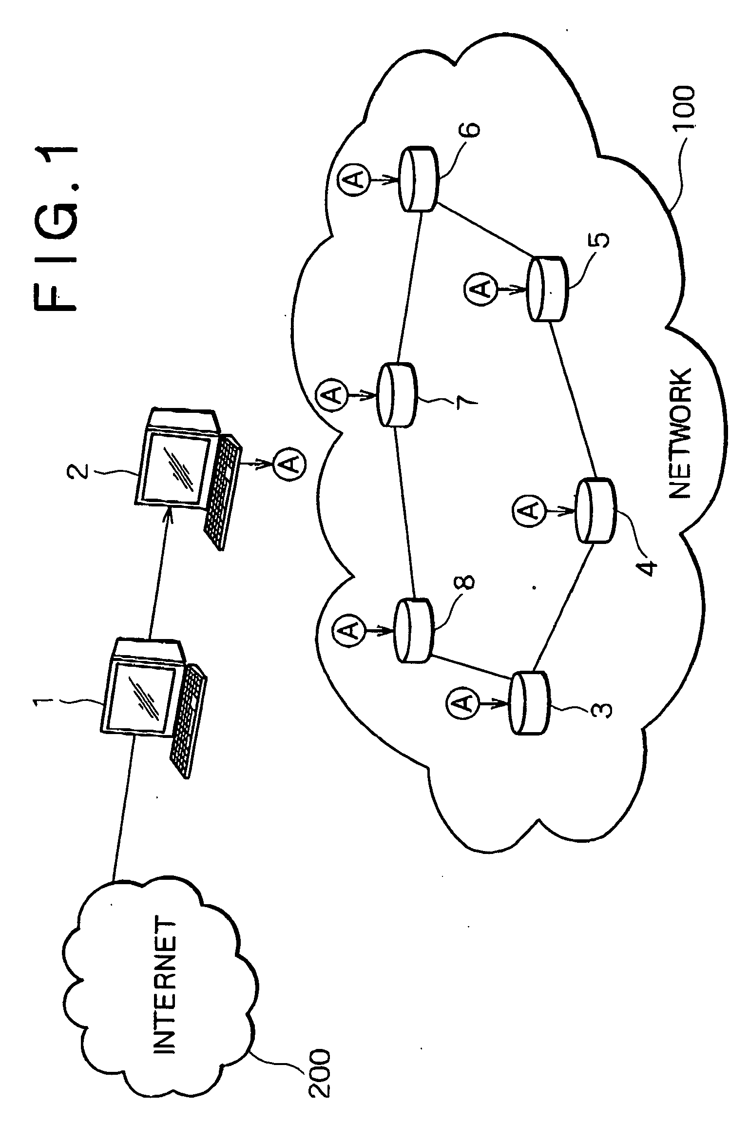
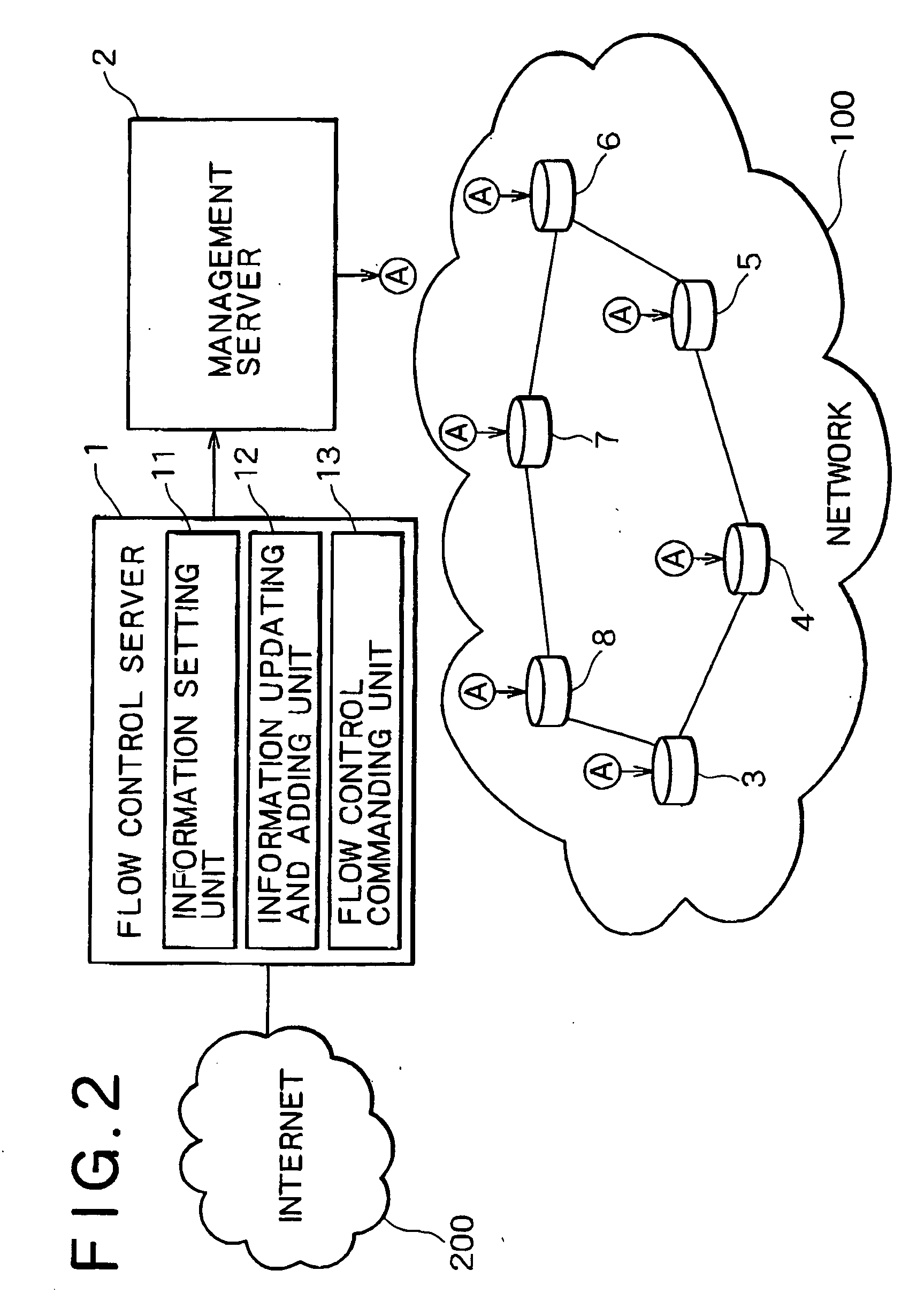
[0035]FIG. 2 is a block diagram showing the structure of a flow control system according to the present invention. The flow control system according to this embodiment comprises a flow control server 1, a management server 2, a network 100 (the network includes a plurality of networks which are connected to each other by the respective routers 3 to 8), and the Internet 200. The flow control server 1 has information setting unit 11, information updating and adding unit 12, and flow control commanding unit 13. The management server 2 has the function of controlling (collectively managing) routing information of each router 3 to 8. The network 100 has the routers 3, 4, 5, 6, 7, and 8 which have function of carrying out flow control by controlling its own routing information (routing control).

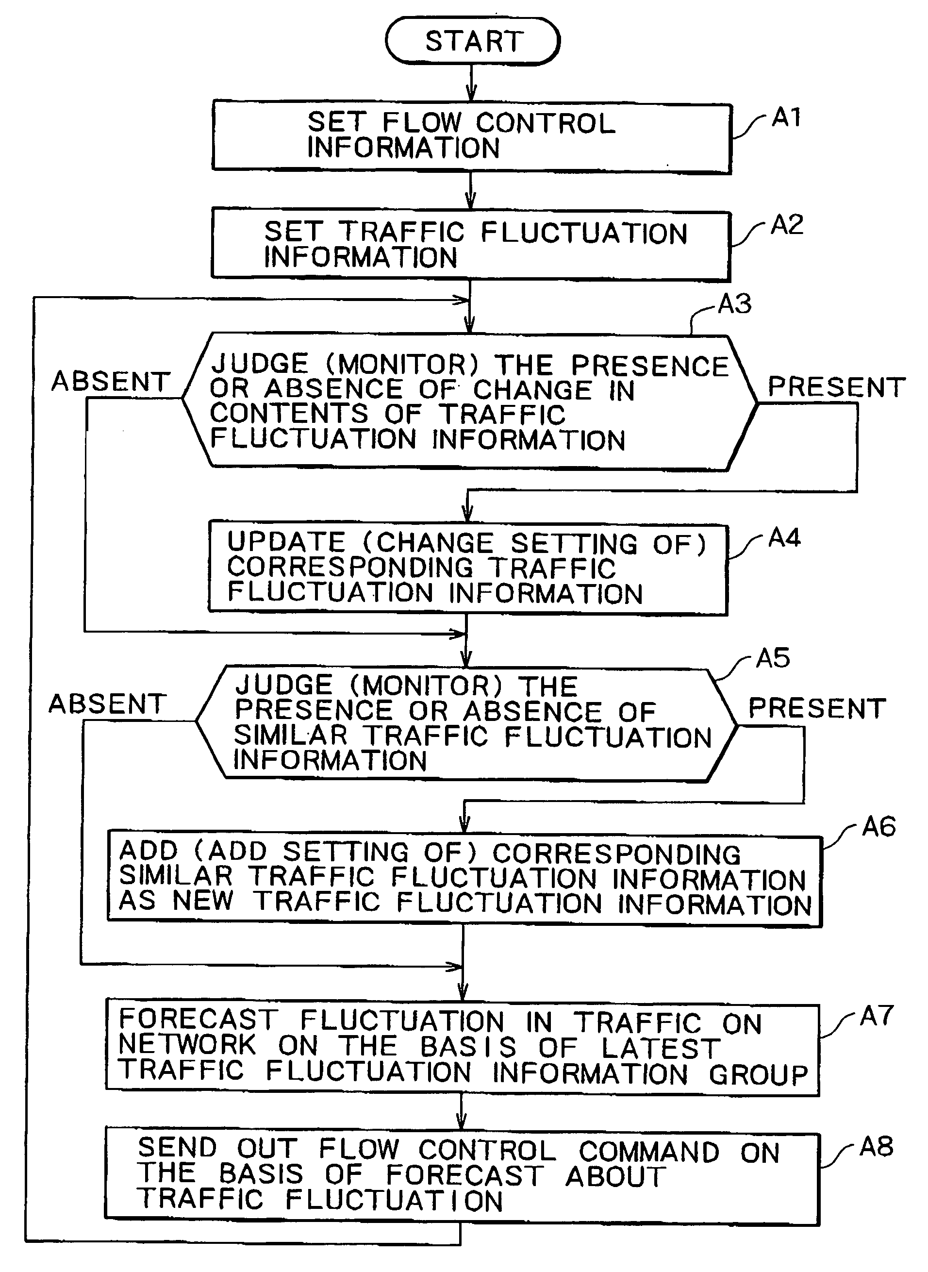
[0036]FIG. 3 is a flowchart which shows processing of the flow control server 1 in the flow control system shown in FIG. 2. The processing includes a step A1 of setting flow control information, a ...

third embodiment

[0062] Next, the present invention will be described. A method for controlling a flow according to this embodiment, which is applied to a network system as shown in FIG. 2, comprises the following steps. In a first step, flow control information is set on a flow control server 1. In a second step, a traffic fluctuation information group is set on the flow control server 1. In a third step, the flow control server 1 monitors the presence or absence of change in the contents of traffic fluctuation information at regular intervals. In a fourth step, setting of the traffic fluctuation information is changed, when the presence of the change in the contents of the traffic fluctuation information is detected in the third step. In a fifth step, the flow control server 1 monitors the presence or absence of similar traffic fluctuation information at regular intervals. In a sixth step, the similar traffic fluctuation information is added to setting as new traffic fluctuation information, when ...

second embodiment

[0068] The operation of the flow control method according to this embodiment is the same as the contents of operation (processing) shown in FIGS. 3 and 7, which are described in the explanation of the flow control system according to the foregoing

[0069] Next, a fifth embodiment of the present invention will be described. FIG. 8 is a block diagram showing a flow control system according to the fifth embodiment. As compared with the flow control system shown in FIG. 2, the flow control system according to the fifth embodiment has a flow control program 800. The flow control program 800 is read into a flow control server 1 of a network system, which comprises the flow control server 1, a management server 2, a network 100 with routers 3 to 8, and the Internet 200. The flow control program 800 controls the operation of the flow control server 1 as information setting unit 11, information updating and adding unit 12, and flow control commanding unit 13. The operation of the information s...


PUM


Abstract

A flow control server forecasts a fluctuation in the traffic on a network to be controlled, on the basis of an information set on itself and a result of searching information on the Internet. The flow control server issues a flow control command to a management server so as to prevent a congestion in the network on the basis of the forecast. The management server controls a routing information of each router on the basis of the flow control command from the flow control server, and sends out a routing control command to each router based on the control. Each router carries out the routing control by setting its own routing information on the basis of the routing control command received from the management server, in order to realize the flow control.

Description

BACKGROUND OF THE INVENTION [0001] 1. Field of the Invention [0002] The present invention relates to a flow control system and a method for controlling a flow in a network system having a router which carries out routing control on the basis of routing information. [0003] 2. Description of the Related Art [0004] Recent development in network service is outstanding, and traffic on a network variously increases and decreases in accordance with the contents of service provided by the network service. [0005] A flow on the network includes a flow related to VoIP (voice over IP (internet protocol)), a flow related to financial business information, and the like. In such flows, a user runs into trouble if delay in the transmission of data transmitted by the flow is long or data is lost. How to control and deal with such flows is an important subject in the field of network technology. [0006] In a conventional method for controlling this type of flow (flow control system), information indic...

Claims


Application Information

Patent Timeline
IPC IPC(8): H04L12/801G06F15/16H04L12/825H04L12/911
CPCH04L45/00H04L47/12H04L47/10H04L45/38
Inventor SUZUKI, YUICHI
Owner NEC CORP
Learn More