Cleaning machine for cleaning a surface

a cleaning machine and surface technology, applied in the direction of carpet cleaners, cleaning filter means, cleaning equipment, etc., can solve the problem of loss of suction power in each nozzle portion

Active Publication Date: 2005-05-05
HEALTHY GAIN INVESTMENTS
View PDF13 Cites 75 Cited by
  • Summary
  • Abstract
  • Description
  • Claims
  • Application Information

AI Technical Summary

Benefits of technology

[0007] The foregoing and other objects of the present invention will be readily apparent from the following description and the attached drawings. In one aspect of the invention, a cleaning machine for cleaning a surface in which cleaning solution is distributed to the surface and substantially simultaneously extracted along with the dirt on the surface in a continuous operation as it moves along the surface is provided. The cleaning machine includes a base assembly that moves along the surface and a liquid distribution system associated with the base assembly for distributing the cleaning solution to the cleaning surface. A suction nozzle assembly is mounted to the base assembly and includes a front nozzle portion and a rear nozzle portion. The front nozzle portion defines a fluid flow path having an inlet opening and an outlet opening and the rear nozzle portion defines a fluid flow path having an inlet opening and an outlet opening. A suction source is in fluid communication with the suction nozzle for applying suction to draw the cleaning solution and dirt from the surface and through the suction nozzle. A valve assembly is associated with the suction nozzle assembly. The valve assembly substantially covers the outlet of the front nozzle portion to close the fluid flow path of the front nozzle portion in response to the base assembly moving in one of the forward direction and rear direction. The valve assembly substantially covers the outlet of the rear nozzle portion to close the fluid flow path of the rear nozzle portion in response to the base assembly moving in the other one of the forward direction and rear direction.

Problems solved by technology

However, the added suction area from the additional nozzle portion results in a loss of suction power in each nozzle portion.

Method used


Image

  • Cleaning machine for cleaning a surface
  • Cleaning machine for cleaning a surface
  • Cleaning machine for cleaning a surface

Examples


Embodiment Construction

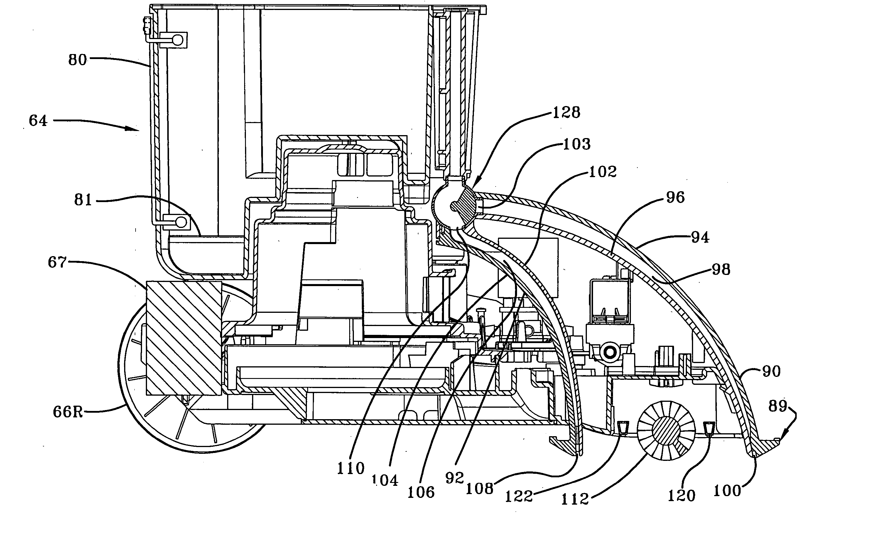
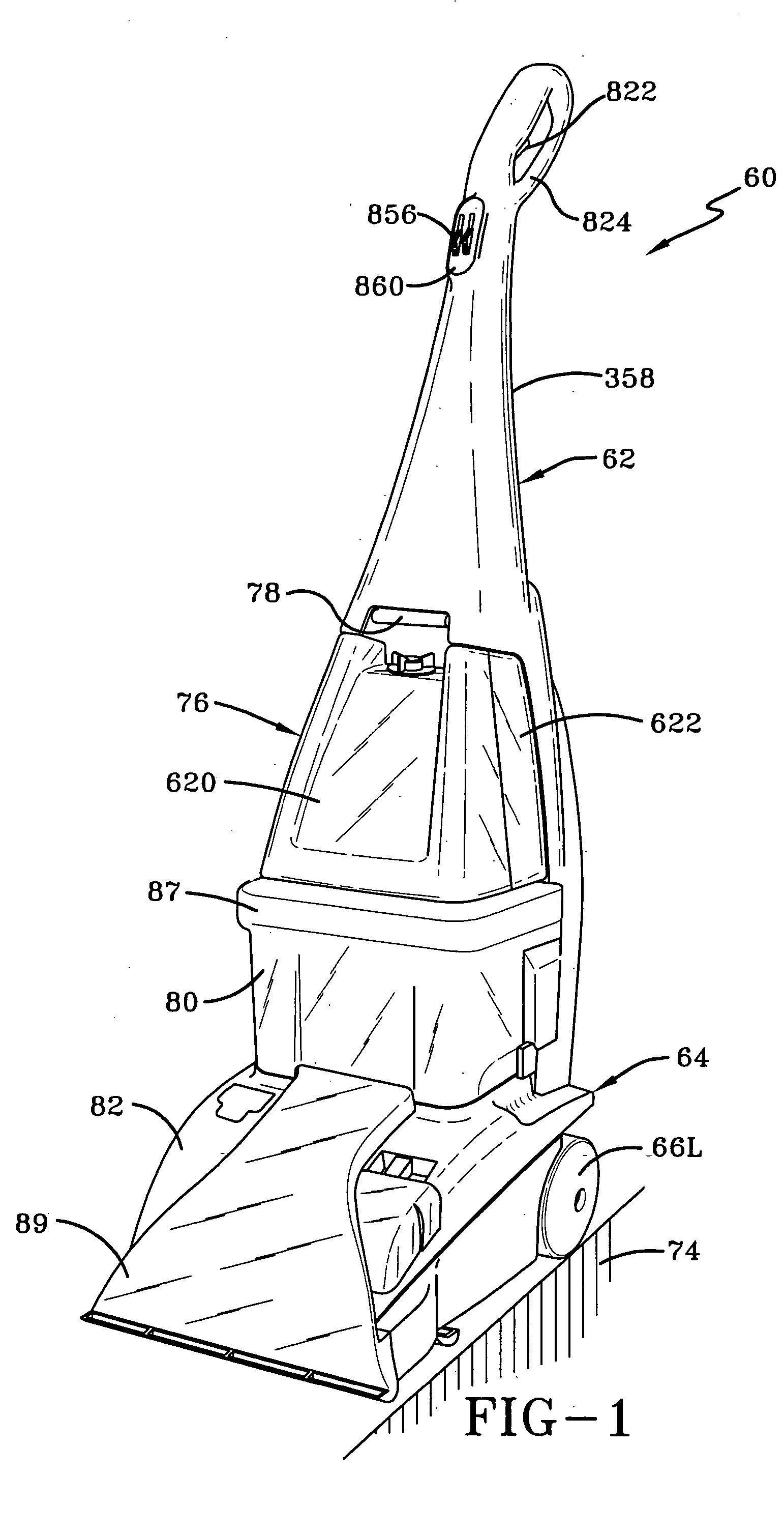
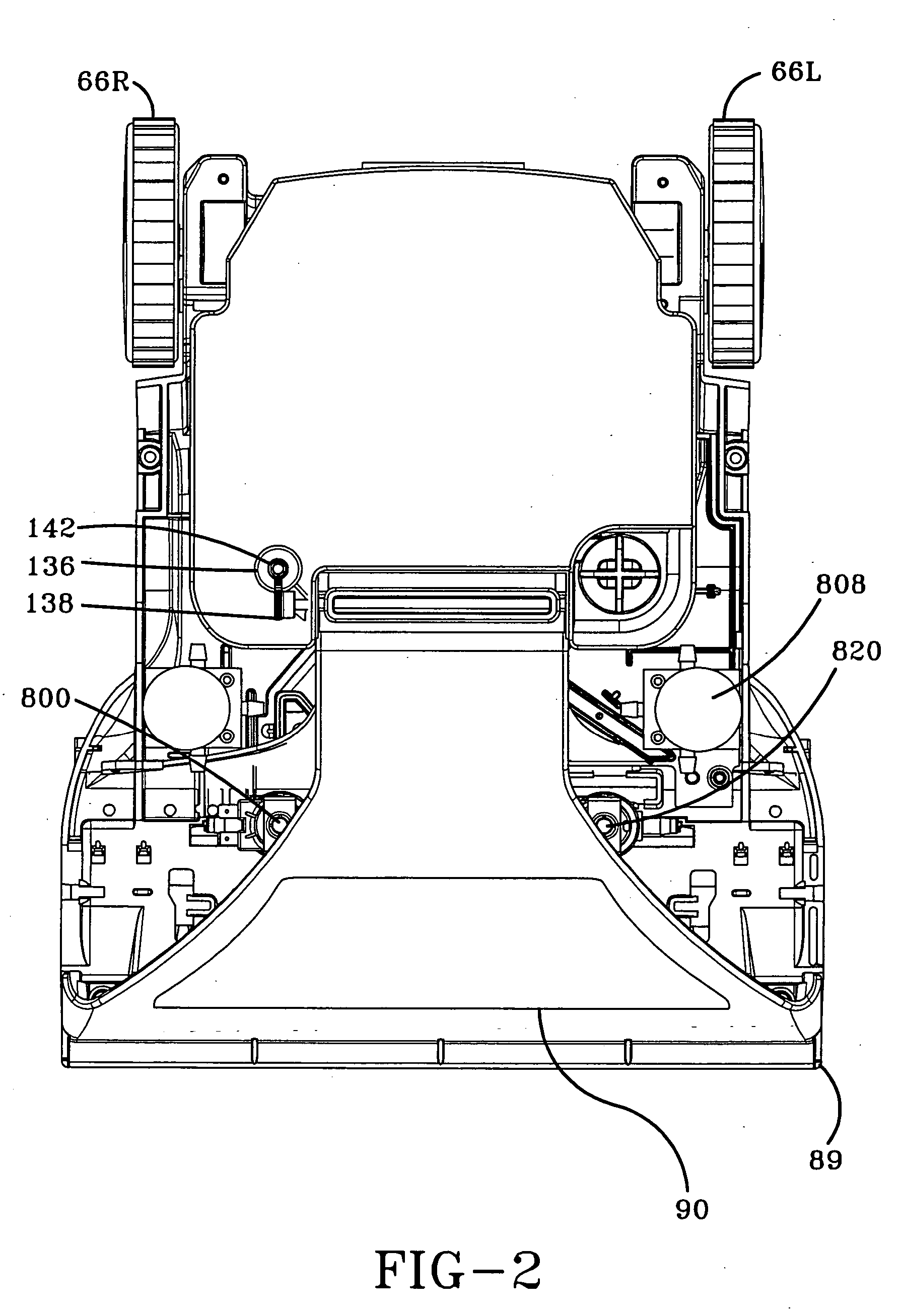
[0032] Referring to the drawings, FIG. 1 depicts a perspective view of an upright carpet extractor 60 according to one embodiment of the present invention. The upright carpet extractor 60 comprises an upright handle assembly 62 pivotally connected to the rear portion of the floor-engaging portion or base assembly 64 that moves and cleans along a surface 74 such as a carpet or bare floor. The base assembly 64 includes two laterally displaced wheels 66L and 66R (FIG. 4) rotatably attached thereto. A transmission assembly 67 (FIG. 4) is mounted to the base assembly 64 and operatively connected to the wheels so that the extractor 60 can be self-propelled.

[0033] A supply or solution tank assembly 76 is removably mounted to the handle portion 62 of the extractor 60. A combined air / water separator and recovery tank 80 with carrying handle 87 removably sets atop a suction motor / fan assembly 81 (FIG. 4) of the base assembly 64 and is surrounded by a hood portion 82. A floor suction nozzle a...


PUM


Abstract

A cleaning machine for cleaning a surface is provided. The cleaning machine includes a base assembly that moves along the surface and a liquid distribution system associated with the base assembly for distributing the cleaning solution to the cleaning surface. A suction nozzle assembly is mounted to the base assembly and includes a front nozzle portion and a rear nozzle portion. The front nozzle portion defines a fluid flow path having an inlet opening and an outlet opening and the rear nozzle portion defines a fluid flow path having an inlet opening and an outlet opening. A suction source is in fluid communication with the suction nozzle for applying suction to draw the cleaning solution and dirt from the surface and through the suction nozzle assembly. The fluid flow path of the front nozzle portion is closed in response to the base assembly moving in one of the forward direction and rear direction. The fluid flow path of the rear nozzle portion is closed in response to the base assembly moving in other one of the forward and rear direction.

Description

BACKGROUND OF THE INVENTION [0001] 1. Field of the Invention [0002] The present invention relates to a cleaning machine for cleaning a surface. [0003] 2. Background Information [0004] It is known to have cleaning machines for cleaning a surface. One example of a cleaning machine is a carpet extractor that distributes cleaning solution to a cleaning surface and substantially simultaneously extracts it along with the dirt on the carpet in a continuous operation as shown in U.S. Pat. No. 5,500,977. In several instances, the carpet extractor is pushed forward to clean one cleaning path and then moved sidewardly and pulled rearwardly to clean another cleaning path. However, usually the suction nozzle is positioned in front of the distribution of the cleaning solution. Thus, cleaning solution is left on cleaning paths in which the extractor was only pushed forward. To solve this problem, a dual suction nozzle assembly incorporating front and rear nozzle portions positioned on each side of...

Claims


Application Information

Patent Timeline
Patent Type & Authority Applications(United States)
IPC IPC(8): A47L5/30A47L11/28A47L11/30A47L11/34
CPCA47L5/30A47L11/4036A47L11/34
Inventor GORDON, EVAN A.MAKAROV, SERGEY V.TONDRA, AARON P.DURBIN, MICHAEL A.
Owner HEALTHY GAIN INVESTMENTS
Why Eureka
Try Eureka