Suspended ceiling fan

a ceiling fan and suspension technology, applied in the direction of suspension devices, machines/engines, machine supports, etc., can solve the problems of user difficulty in moving parts, chen '062 devices cannot be easily moved, and the operator has little control over the direction of airflow produced by the device, etc., to achieve the effect of easy movemen

Inactive Publication Date: 2005-05-05
GONCE KEN R
View PDF15 Cites 72 Cited by
  • Summary
  • Abstract
  • Description
  • Claims
  • Application Information

AI Technical Summary

Benefits of technology

[0014] It is a further object of the invention to provide a suspended ceiling fan that can be easily moved by a person to a different location.
[0015] Still another object of the invention is to provide a suspended ceiling fan that can provide a sustained vectored flow of air that can be aimed at one spot such as a person's face.
[0016] A further object

Problems solved by technology

For example, once the traditional ceiling fan is installed, the operator can switch the device on or off, and may be able to set the speed of the device, but the operator has little, if any, control over the direction of airflow produced by the device.
Also, traditional ceiling fans are typically complex in construction and suffer from high loads, leading to stress on moving parts.
In addition, traditional ceiling fans are designed to be located in one spot and cannot be moved to a different part of a ceiling.
Further, a user cannot easily move the Chen '062 device to a different location.
Still further, short of jamming the rack body the Chen '062 device

Method used


Image

  • Suspended ceiling fan
  • Suspended ceiling fan
  • Suspended ceiling fan

Examples


Embodiment Construction

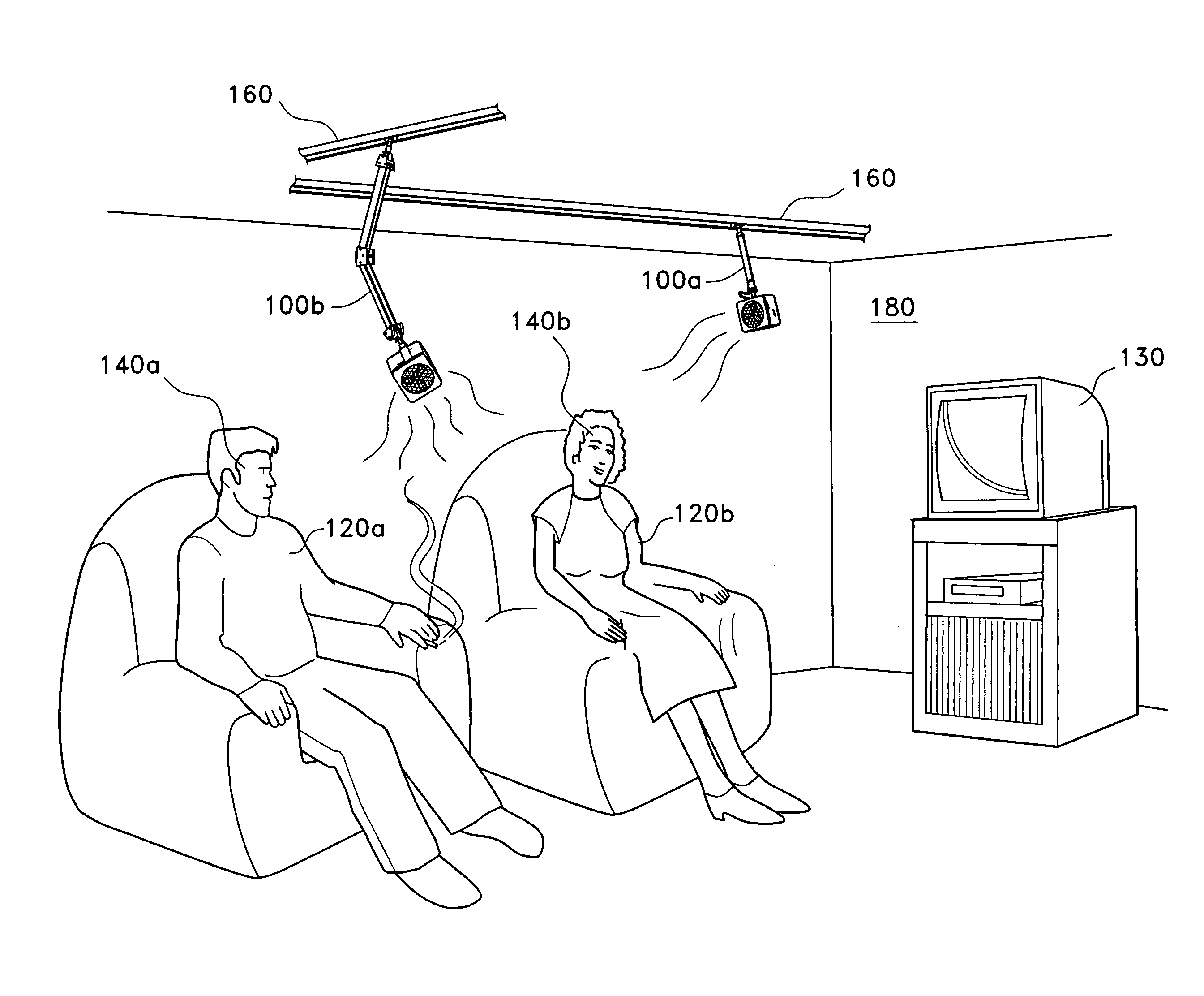
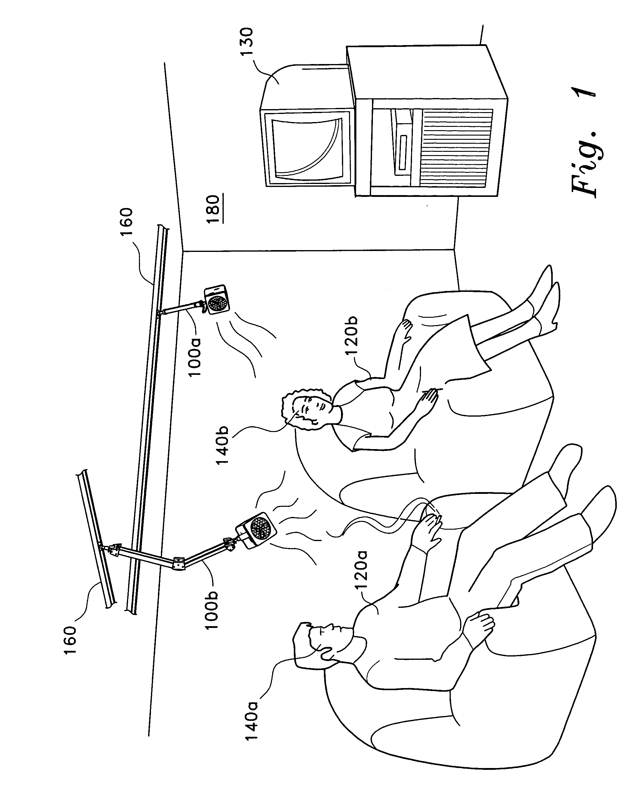
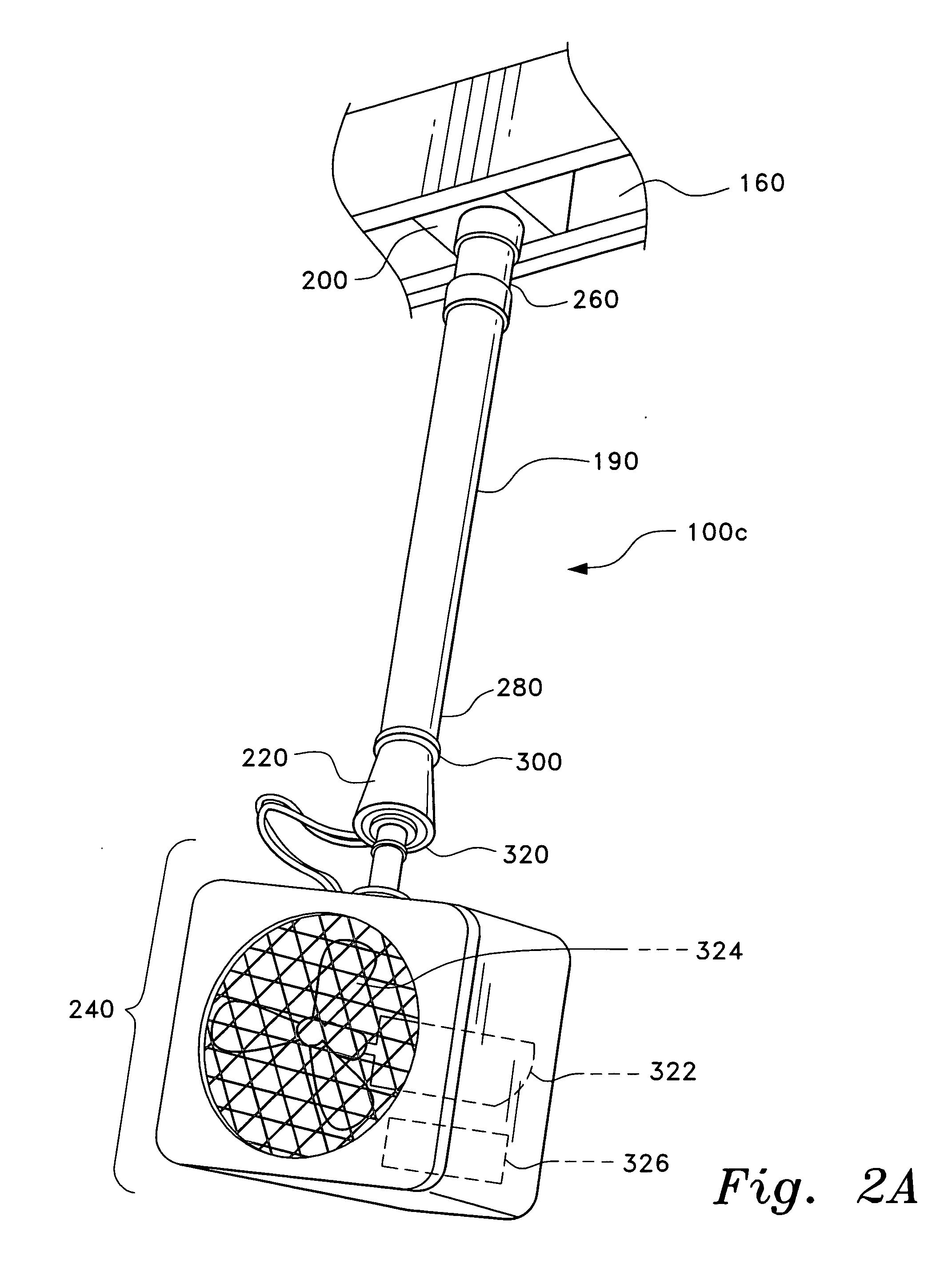
[0028] The present invention relates generally to ceiling fans. More specifically, the invention is a ceiling fan configured to attach to a track attached to a ceiling. The track could be a conventional lighting track currently known in the art.

[0029]FIG. 1 is an environmental perspective view of two embodiments of ceiling fan 100a and 100b, respectively, according to the present invention. The suspended ceiling fans 100a and 100b are being used by two users 120a and 120b, respectively, to separately direct airflow from the fans 100a and 100b while engaged in the pastime of watching a television 130. Specifically, the users 120a and 120b are using the suspended ceiling fans 100a and 100b to apply sustained directed air flow to their faces 140a and 140b, respectively. When fitted with an integral battery or other suitable power source the suspended ceiling fans 100a and 100b can be moved to a convenient location in a room 180 by a user, thereby obviating the need to rely on higher e...


PUM


Abstract

The suspended ceiling fan generates a sustained flow of air, which can be aimed at one spot, such as a person's face. In one embodiment, the suspended ceiling fan has an elongated member, a track connector, a swivel, and a fan unit. The elongated member has first and second opposing ends. The track connector is attached to the first end, and is adapted for attachment to an existing track, such as a track lighting system, or other support for a suspended lighting system. In one mode of operation the connector snaps into the track. In another embodiment, the ceiling fan comprises an adjustable arm having a hinged joint. The fan may be moved along the track and pivoted on the swivel to direct airflow in any desired direction.

Description

CROSS-REFERENCE TO RELATED APPLICATION [0001] This application claims the benefit of U.S. Provisional Patent Application Ser. No. 60 / 516,268, filed Nov. 3, 2003.BACKGROUND OF THE INVENTION [0002] 1. Field of the Invention [0003] The present invention relates generally to ceiling fans. More specifically, the invention is a suspended ceiling fan configured to attach to a track attached to a ceiling. [0004] 2. Description of the Related Art [0005] Traditional ceiling fans are good at providing an omnidirectional flow of moving air. The operator or user of traditional ceiling fans can only decide the operating status of the ceiling fan. For example, once the traditional ceiling fan is installed, the operator can switch the device on or off, and may be able to set the speed of the device, but the operator has little, if any, control over the direction of airflow produced by the device. Also, traditional ceiling fans are typically complex in construction and suffer from high loads, leadin...

Claims


Application Information

Patent Timeline
IPC IPC(8): A47H1/10F24F
CPCF04D25/088
Inventor GONCE, KEN R.
Owner GONCE KEN R
Why Eureka
Try Eureka