Staple remover

a staple remover and staple technology, applied in the field of staple removers, can solve the problems of loose staples falling into the copying machine, diskettes, and inadvisable use of magnets near computers,

Active Publication Date: 2005-05-05
NESS ANTON PAUL
View PDF4 Cites 8 Cited by
  • Summary
  • Abstract
  • Description
  • Claims
  • Application Information

AI Technical Summary

Benefits of technology

[0008] In a second embodiment similar to the first, a flat platform accompanies the handheld remover to support the document during destapling; the rem

Problems solved by technology

Some staple removers include magnetic portions to temporarily hold the loose staple until manually pulled away and disposed of; but magnets are not advisable near computers, diskettes and the like.
Commonly some damage may occur to the document that is destapled by these prior art devices.
But even more damage has c

Method used


Image

  • Staple remover
  • Staple remover
  • Staple remover

Examples


Embodiment Construction

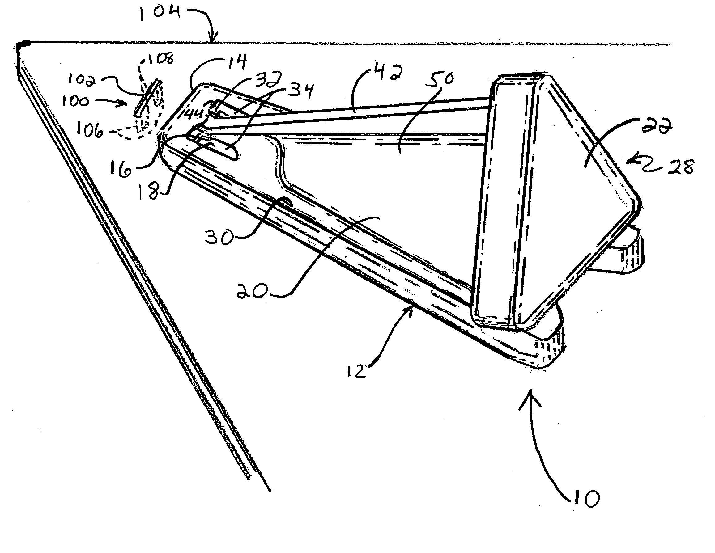
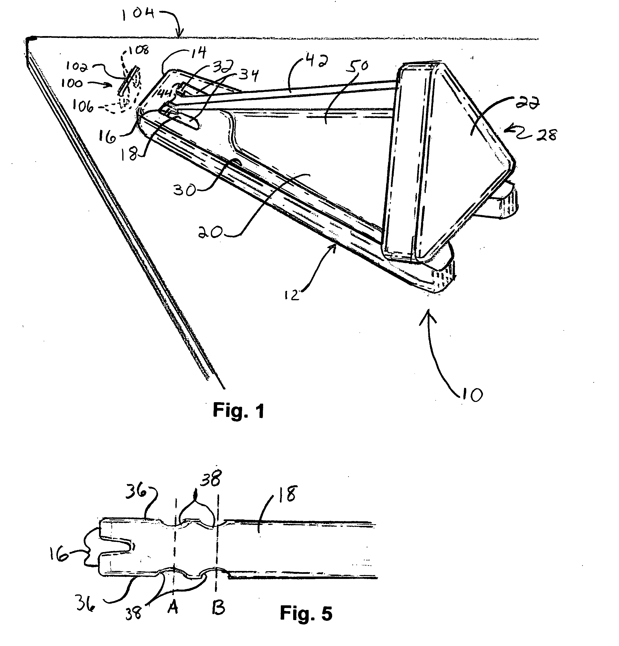
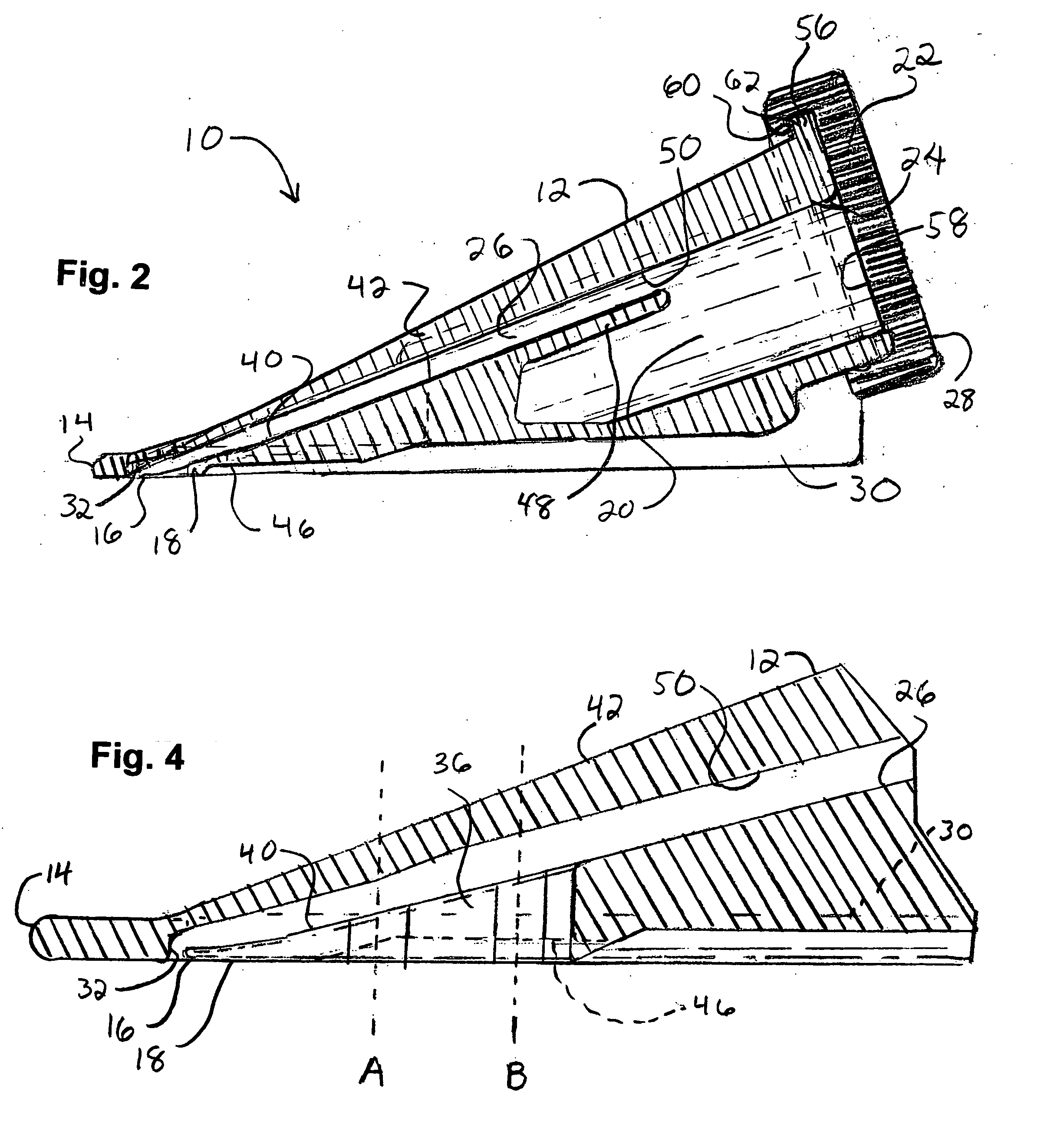
[0023] In FIGS. 1 to 6 is shown a first embodiment of the staple remover of the present invention, including the nonsnagging wedge of the present invention. Remover 10 includes a housing body 12 with a forward nose 14 near which is the leading edge 16 of a wedge 18; a rearward bin section 20 that defines an enclosed staple capture space; a rear cap 22 covering the rear opening 24 of the bin section 20; and a clearance 26 that encloses the region above, beside and rearwardly of the wedge 18 in communication with the bin section 20. Remover 10 is pushable relatively along the document's surface by the palm of the hand pressing against a rear, palm-engageable surface 28 of rear cap 22 and has an ergonomic design; a widened bottom skirt portion 30 with smooth outwardly-facing surfaces rests on and easily glides over the top of the document to be destapled, with the document either being handheld or resting on a support surface such as a desktop (or a platform; see FIG. 9).

[0024] As bes...


PUM


Abstract

A staple remover (10) for removing a staple (100) from a document (102) and simultaneously capturing the thus-removed staple. The staple remover includes a wedge (18) for prying the staple free from a document without the staple snagging to the wedge, a bin (20) into which the freed staple will fall and, when in the form of a handheld device, an enclosed clearance (26) around the wedge's top or bearing surface that lifts the staple and that is in communication with the bin such that when the remover is immediately tilted front end upwardly as the staple is freed, the staple falls through the clearance and into the bin. The surfaces of the wedge that engage or could possibly engage the staple's leg portions, are adapted to prevent snagging of the staple when freed from the document. The bin could include an opening (24) covered by a cap (22) that is removable to permit emptying.

Description

RELATED APPLICATION DATA [0001] This application claims priority from United States Provisional Patent Application Ser. No. 60 / 516,870 filed Nov. 3, 2003.FIELD OF THE INVENTION [0002] This relates to the field of office accessories and more particularly to implements for removing staples from documents. BACKGROUND OF THE INVENTION [0003] Manual staple removers for standard staples have conventionally been of two basic types: a hinged device with a pair of grippers that are squeezed toward each other for their leading ends to pry cooperatively beneath the staple after which the device is pulled from the document and lifts the staple vertically from the document; and, a unitary device with an elongate prying lever to be inserted and urged beneath the staple and pushed forwardly as the gradually widening or raising portions of the lever lift the staple until the staple is pried free from the document, and may sometimes be found fastened to the side of a stapling device. The freed stapl...

Claims


Application Information

Patent Timeline
IPC IPC(8): B25C11/00
CPCB25C11/00
Inventor NESS, ANTON PAUL
Owner NESS ANTON PAUL
Why Eureka
Try Eureka