Stacked bulk acoustic resonator band-pass filter with controllable pass bandwidth

a bandpass filter and bulk technology, applied in the direction of piezoelectric/electrostrictive device material selection, device material selection, generator/motor, etc., can solve the problems of unsuitable sbar for use in most band-pass filtering applications, sbar is unsuitable for most applications, and the physical size of such products has tended to decrease significantly

Active Publication Date: 2005-05-05
AVAGO TECH INT SALES PTE LTD
View PDF17 Cites 108 Cited by
  • Summary
  • Abstract
  • Description
  • Claims
  • Application Information

AI Technical Summary

Benefits of technology

[0013] In a final aspect, the invention provides a method of fabricating an acoustically-coupled device. In the method, a first film bulk acoustic resonator (FBAR) is fabricated and an acoustic decoupler is fabricated on the first FBAR. A second FBAR is fabricated on the acoustic decoupler. Fabricating the second FBAR o

Problems solved by technology

In recent years, the physical size of such products has tended to decrease significantly while the circuit complexity of the products has tended to increase.
However, practical examples of the SBAR

Method used


Image

  • Stacked bulk acoustic resonator band-pass filter with controllable pass bandwidth
  • Stacked bulk acoustic resonator band-pass filter with controllable pass bandwidth
  • Stacked bulk acoustic resonator band-pass filter with controllable pass bandwidth

Examples


exemplary embodiment 100

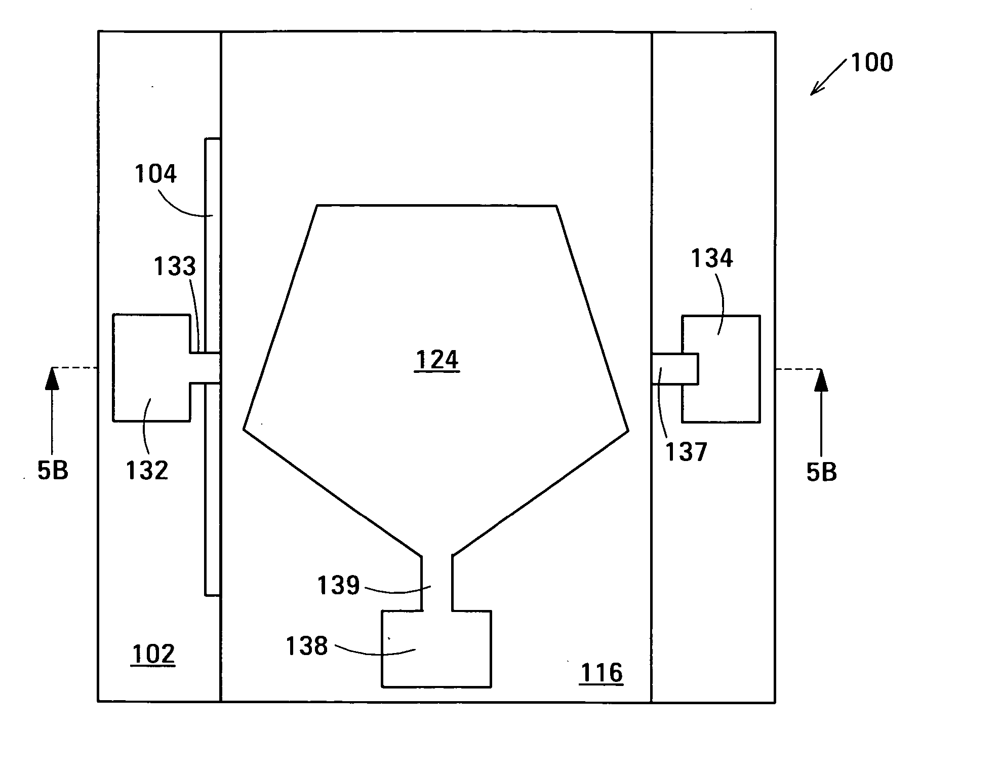
[0028]FIG. 5A is a schematic side view showing the structure of an exemplary embodiment 100 of a band-pass filter in accordance with the invention. FIG. 5B is a cross-sectional view along the section line 5B-5B in FIG. 5A. Band-pass filter 100 is composed of a stacked pair of film bulk acoustic resonators (FBARs) 110 and 120. In the example shown, FBAR 120 is stacked atop FBAR 110. FBAR 110 is composed of opposed planar electrodes 112 and 114 and a layer 116 of piezoelectric material between the electrodes. FBAR 120 is composed of opposed planar electrodes 122 and 124 and a layer 126 of piezoelectric material between the electrodes. Band-pass filter 100 is also composed of an acoustic decoupler 130 between FBARs 110 and 120, specifically, between electrodes 114 and 122. The acoustic decoupler controls the coupling of acoustic energy between FBARs 110 and 120. Specifically, the acoustic decoupler couples less acoustic energy between the FBARs than would be coupled by direct contact b...

exemplary embodiment 200

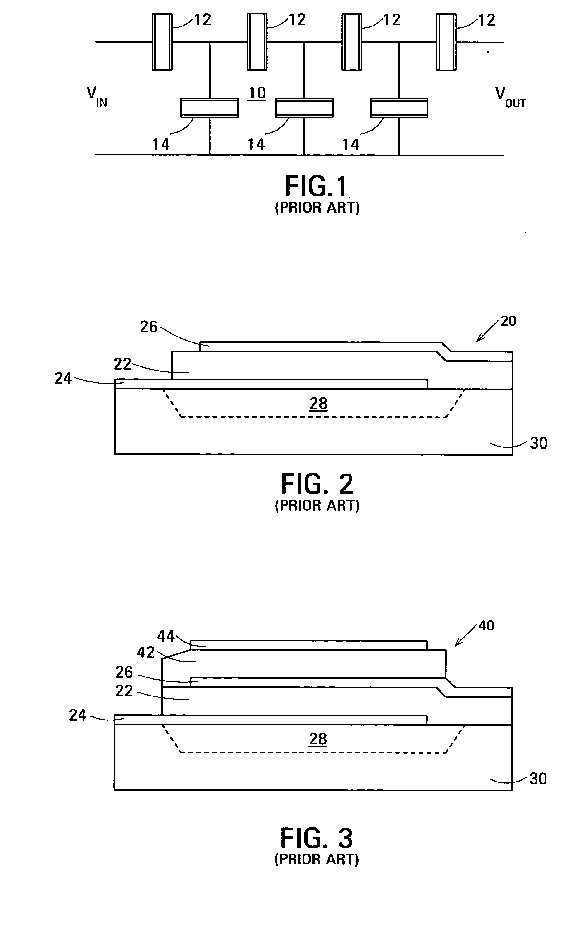
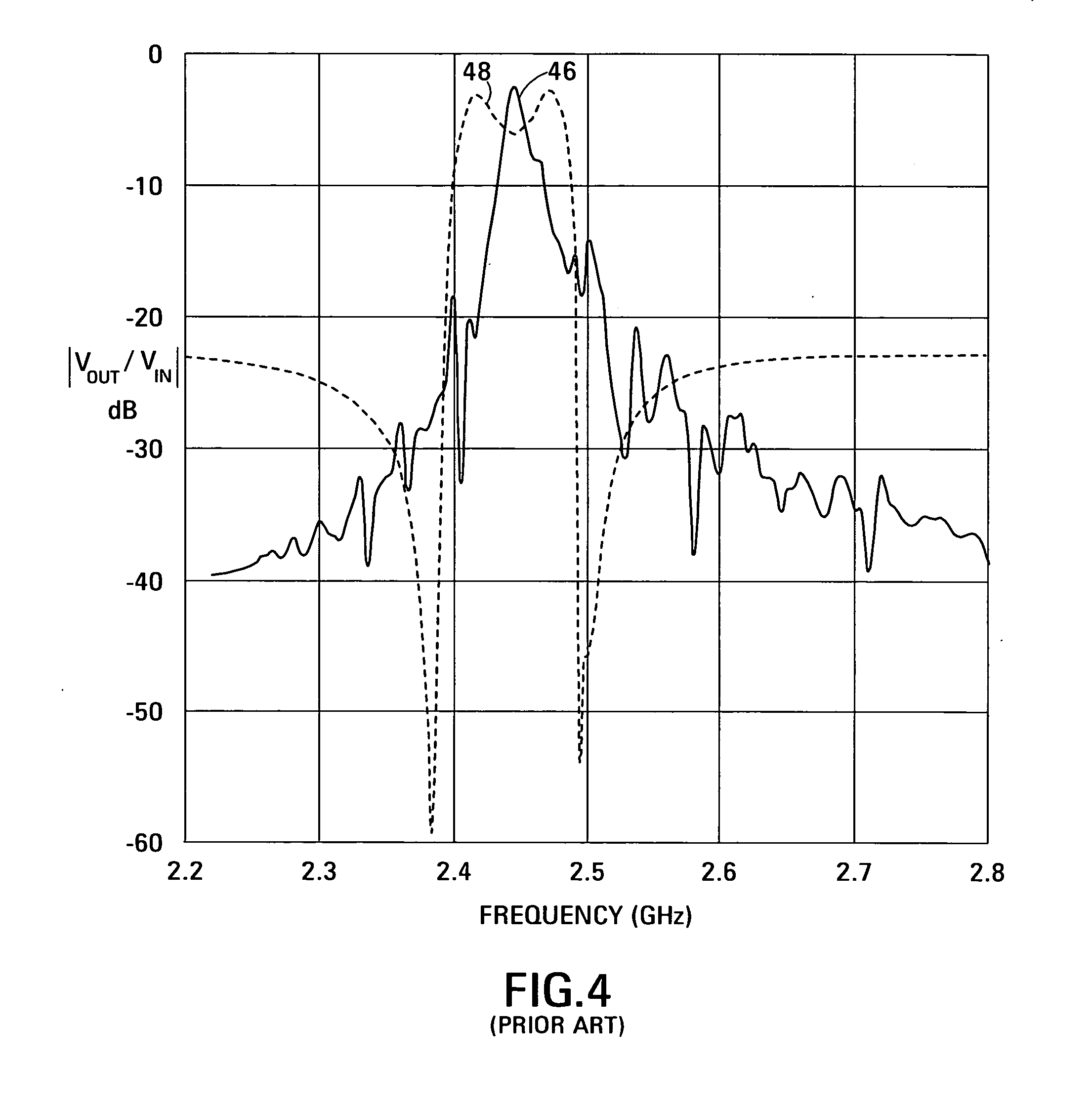
[0082] A comparison of FIG. 6 with curve 46 of FIG. 4 shows that the slope of the out-of-band frequency response of band-pass filter 100 is less steep than that of the band-pass ladder filter 10 shown in FIG. 1. The comparison also shows that, unlike that of band-pass ladder filter 10, the frequency response of band-pass filter 100 does not rise again after the initial sharp fall. FIG. 8 is a schematic drawing of an exemplary embodiment 200 of a band-pass filter in accordance with the invention having an out-of-band frequency response that has a steeper slope than that of band-pass filter 100, and in which, after the initial sharp fall, the frequency response rises to a substantially lower level than the band-pass ladder filter shown in FIG. 1.

[0083] Band-pass filter 200 is composed of a simplified FBAR-based ladder filter 210 connected in series with band-pass filter 100 described above with reference to FIGS. 5A and 5B. Ladder filter 210 is composed of series FBARs 212 and 214 and...


PUM

PropertyMeasurementUnit
Massaaaaaaaaaa
Temperatureaaaaaaaaaa
Thicknessaaaaaaaaaa

Abstract

The band-pass filter has a stacked pair of film bulk acoustic resonators (FBARs) and an acoustic decoupler between the FBARs. Each of the FBARs has opposed planar electrodes and a layer of piezoelectric material between the electrodes. The acoustic decoupler controls the coupling of acoustic energy between the FBARs. Specifically, the acoustic decoupler couples less acoustic energy between the FBARs than would be coupled by direct contact between the FBARs. The reduced acoustic coupling gives the band-pass filter desirable in-band and out-of-band properties.

Description

RELATED APPLICATION [0001] This application is related to U.S. patent application Ser. No. 10 / XXX,XXX of John D. Larson III and Richard Ruby entitled Thin-Film Acoustically-Coupled Transfonner (Agilent Docket No. 10030993), filed on the filing date of this application and incorporated into this application by reference.BACKGROUND [0002] Electrical band-pass filters are used in many different types of consumer and industrial electronic product to select or reject electrical signals in a range of frequencies. In recent years, the physical size of such products has tended to decrease significantly while the circuit complexity of the products has tended to increase. Consequently, a need for highly miniaturized, high-performance band-pass filters exists. A special need for such band-pass filters exists in cellular telephones in which the antenna is connected to the output of the transmitter and the input of the receiver through a duplexer that includes two band-pass filters. [0003] Moder...

Claims


Application Information

Patent Timeline
IPC IPC(8): H01L41/18H01L41/09H01L41/22H03H9/13H03H9/17H03H9/54H03H9/58H03H9/60
CPCH03H9/132H03H9/584H03H9/587Y10T29/49117Y10T29/49005Y10T29/42H03H9/605
Inventor LARSON, JOHN D. III
Owner AVAGO TECH INT SALES PTE LTD
Why Eureka
Try Eureka