Low power consumption, broad navigability optical mouse

a mouse and wide-ranging technology, applied in the field of motion-detecting optical devices, can solve the problems of painting metal and present functional challenges to typical current optical navigation devices

Active Publication Date: 2005-05-05
PIXART IMAGING INC
View PDF7 Cites 74 Cited by
  • Summary
  • Abstract
  • Description
  • Claims
  • Application Information

AI Technical Summary

Problems solved by technology

Smooth surfaces such as whiteboard, high gloss paper, plastic, wood grain, or painted metal present functional challenges to typical current optical navigation devices.

Method used


Image

  • Low power consumption, broad navigability optical mouse
  • Low power consumption, broad navigability optical mouse
  • Low power consumption, broad navigability optical mouse

Examples


embodiment 400

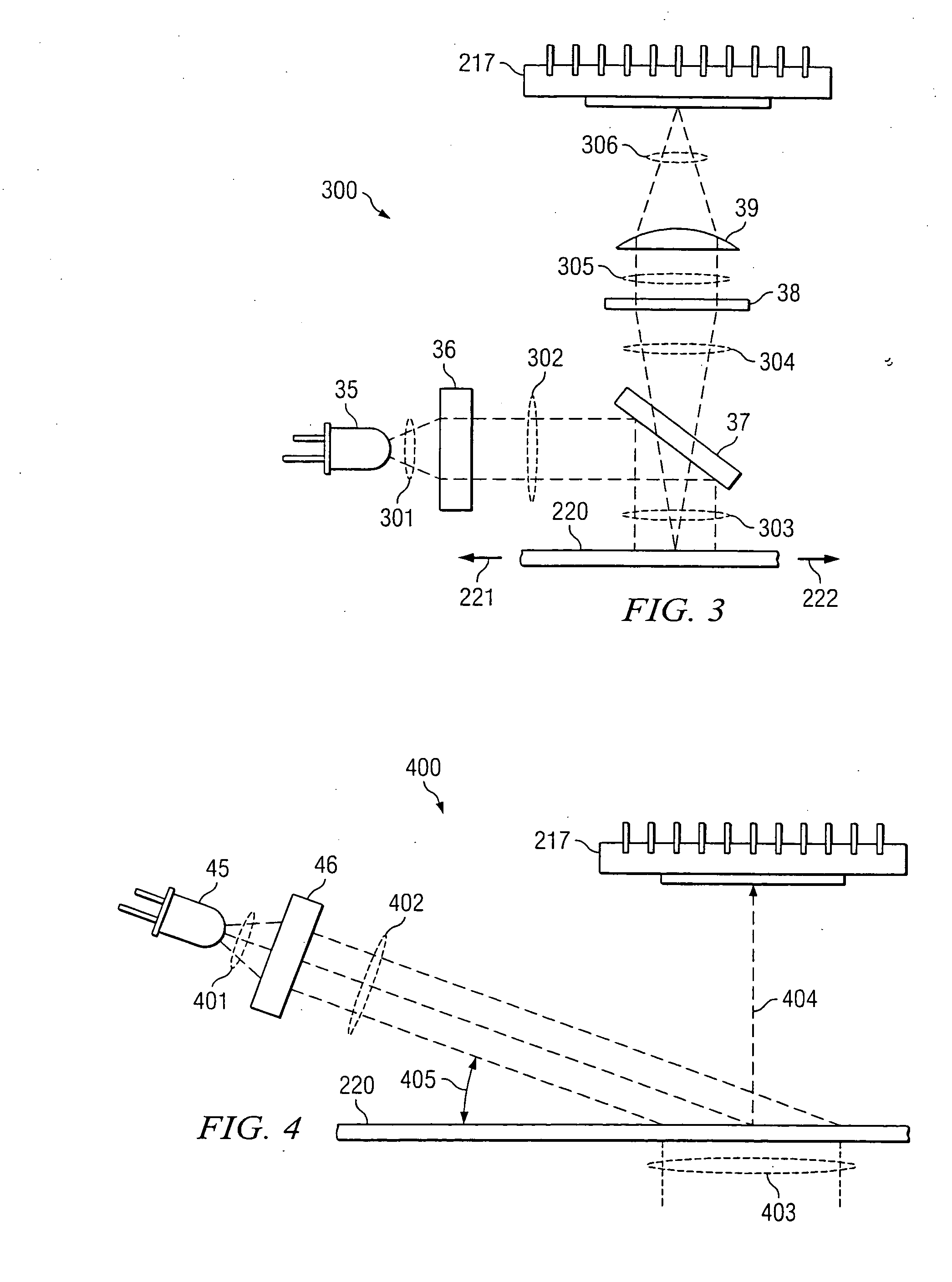
[0037]FIGS. 3 and 4 are diagrams depicting detector 217 associated with illumination optics, for example, in source module 103. FIG. 4 depicts illumination at grazing angle 405. FIG. 3 shows illumination by incoherent light source 35 in source module 103, which is directed normal to the surface of the navigation terrain 220. If navigation terrain 220 contains paper fibers to be detected by detector array 217, illumination at grazing angle of incidence 405 is typically desired. While not essential, one or more light emitting diodes (LEDs) 45 may be used in source module 103. Illumination source 35 and / or 45 may each, for example include a plurality of individual illumination elements. Grazing angle 405, which is the complement of the angle of incidence, is typically in the range of five degrees to twenty degrees, but may vary depending upon the properties of navigation terrain 220. In illumination embodiment 400 depicted in FIG. 4, source 45 is shown with illumination optics 46, whic...

embodiment 300

[0038] In illumination embodiment 300 depicted in FIG. 3, light 301 from LED source 35 is collimated by illumination optics 36, and collimated beam 302 is then redirected by optical amplitude beam-splitter 37. For clarity, that portion of the light energy from LED 35 directed to and transmitted through beam-splitter 37 is not shown in FIG. 3. Light energy 303 reflected from beam-splitter 37 illuminates navigation terrain 220 normal to the surface.

[0039] Also represented in FIG. 3 is the portion of light energy 304 that is reflected or scattered from navigation terrain 220 and passed through beam-splitter 37 for aperturing and filtering at element 38 into filtered beam 305. Filtered beam 305 is then directed by navigation optics 39 into detected beam 306 to form a pattern on detector array 217. For clarity, the portion of light energy passing from navigation terrain 220 to beam-splitter 37 and reflecting from the beam-splitter is not shown. The magnification of navigation optics 39 i...


PUM


Abstract

An optical navigation system for determining movement relative to a navigation terrain includes a first source and a second source of optical radiation for illuminating the navigation terrain, the first source differing from the second source in at least one operating parameter. The system further includes means to select the first source and the second source independently based on decision criteria. The system further includes a detector for capturing patterns in the optical radiation subsequent to illuminating of the navigation terrain.

Description

CROSS-REFERENCE TO RELATED APPLICATIONS [0001] This application is related to co-pending and commonly assigned U.S. patent application Ser. No. 10 / 439,674, filed May 16, 2003, titled “INTERFEROMETER BASED NAVIGATION DEVICE,” U.S. patent application Ser. No. ______ [Attorney Docket No. 10030691-I], filed Jul. 30, 2003, titled “METHOD AND DEVICE FOR OPTICAL NAVIGATION,” and U.S. Continuation-in-Part patent application Ser. No. ______ [Attorney Docket No. 10031303-1], filed Oct. 6, 2003; titled “METHOD AND DEVICE FOR OPTICAL NAVIGATION,” the disclosures of which are hereby incorporated herein by reference.TECHNICAL FIELD [0002] This disclosure relates to motion sensing optical devices and more particularly to systems and methods for a low power consumption, broad navigability optical mouse. BACKGROUND OF THE INVENTION [0003] Existing optical devices for relative motion detection utilize pattern correlation techniques to determine relative motion between the device and a surface by capt...

Claims


Application Information

Patent Timeline
Patent Type & Authority Applications(United States)
IPC IPC(8): G01B9/02G06F3/038G06F3/042
CPCG06F3/03544G06F3/0421G06F3/038
Inventor BANEY, DOUGLAS M.XIE, TONGDEPUE, MARSHALL T.
Owner PIXART IMAGING INC
Why Eureka
Try Eureka