Optical system with image producing surface control unit

Inactive Publication Date: 2005-05-05
SAMSUNG ELECTRONICS CO LTD
View PDF3 Cites 2 Cited by
  • Summary
  • Abstract
  • Description
  • Claims
  • Application Information

AI Technical Summary

Benefits of technology

[0008] Accordingly, it is an aspect of the present invention to provide an inclined optical system capable of attaining a clear im

Problems solved by technology

However, the conventional inclined optical system has a problem in that reference points of distances used in the specific equation are indefinite, thus the CCD camera may not

Method used


Image

  • Optical system with image producing surface control unit
  • Optical system with image producing surface control unit
  • Optical system with image producing surface control unit

Examples


Embodiment Construction

[0024] Reference will now be made in detail to the preferred embodiment of the present invention, examples of which are illustrated in the accompanying drawings, wherein like reference numerals refer to like elements throughout. The embodiment is described below in order to explain the present invention by referring to the figures.

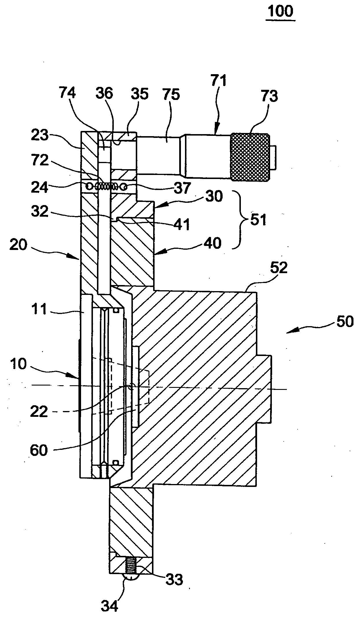
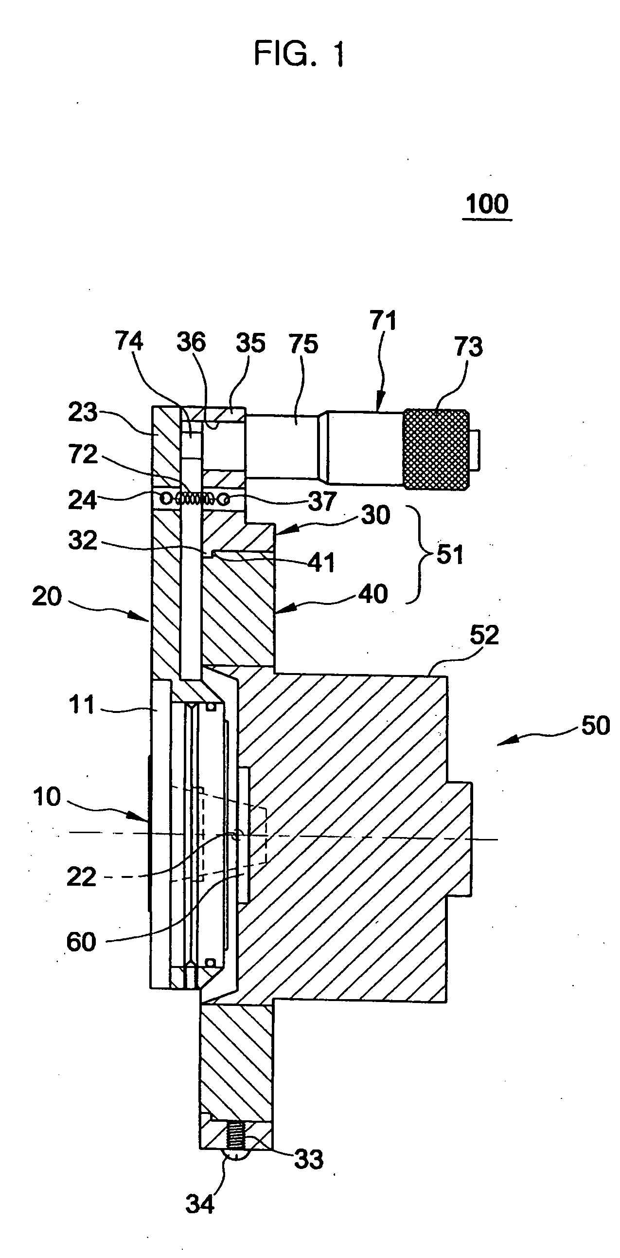
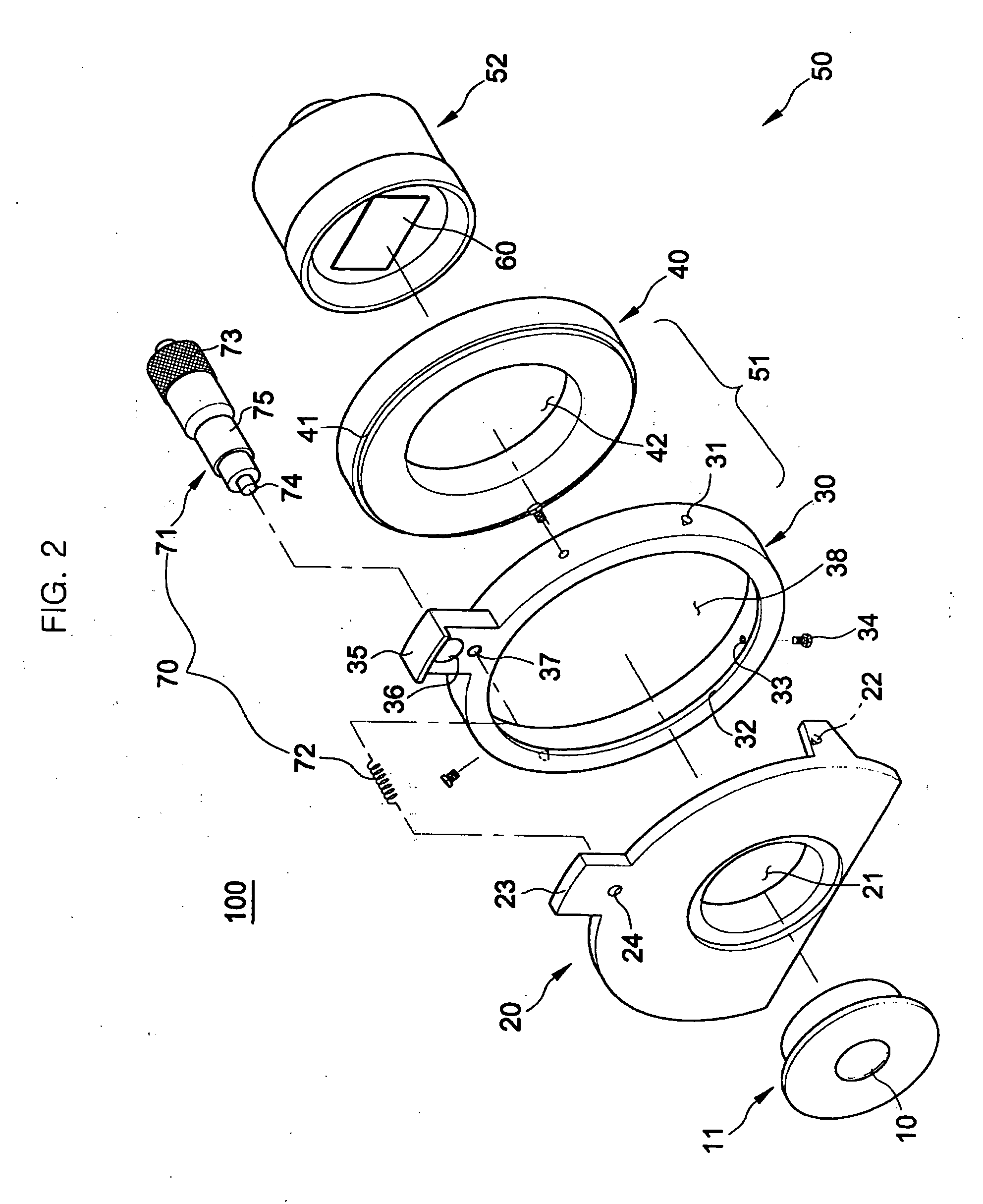
[0025]FIG. 1 is a sectional view of an optical system 100 having an image producing surface control unit according to an embodiment of the present invention. FIG. 2 is an exploded perspective view of the optical system 100 of FIG. 1.

[0026] As shown in FIGS. 1 and 2, the optical system 100 includes a lens 10, a lens holder 11, a base 20, a body 50, and an angle control unit 70. The lens 10 refracts light radiating from an object T to be inspected, and is mounted to the lens holder 11. To the base 20 is mounted the lens holder 11. The body 50 is rotatably mounted to the base 20. The angle control unit 70 is provided on upper portions of both the base 20 an...


PUM


Abstract

An optical system to attain a clear image of an object when the object is photographed in a state where an optical axis of a lens is inclined relative to the object, includes a lens which refracts light radiating from the object, an image producing surface on which the image of the object is produced according to the light refracted by the lens, and an image producing surface control unit which controls the image producing surface to move with respect to the lens. The image producing surface control unit includes an angle control unit to control an angle between an optical axis of the lens and the image producing surface.

Description

CROSS-REFERENCE TO RELATED APPLICATIONS [0001] This application claims the benefit of Korean Patent Application No. 2003-77705, filed Nov. 4, 2003 in the Korean Intellectual Property Office, the disclosure of which is incorporated herein by reference. BACKGROUND OF THE INVENTION [0002] 1. Field of the Invention [0003] The present invention relates, in general, to an optical system to inspect defective parts of a flat panel display (FPD), such as a liquid crystal display (LCD) and, more particularly, to an optical system to attain a uniform and clear image of an object when the object inclined relative to an optical axis of a lens of the optical system is photographed. [0004] 2. Description of the Related Art [0005] When defective parts on an FPD, such as an LCD, are inspected, an inspection result of the FPD may be varied according to viewing angles due to a characteristic of a viewing angular field of the FPD. Thus, when the FPD is photographed to inspect the defective parts thereo...

Claims


Application Information

Patent Timeline
IPC IPC(8): G01M11/00G01N21/95G03B3/04G02B9/34G02B27/10G03B13/32
CPCG01N2021/9513G01N21/95G01M11/00
Inventor AHN, HYEONG-MINLEE, DONG-HEEKIM, CHANG-HYOJEON, HYOUNG-JO
Owner SAMSUNG ELECTRONICS CO LTD
Why Eureka
Try Eureka