

Voice signal clipping circuit and telephone set therewith
a voice signal and circuit technology, applied in the direction of substation equipment, electrical transducers, limiting amplitude without controlling loops, etc., can solve problems such as difficulty in catching voice, and achieve the effect of high communication quality
- Summary
- Abstract
- Description
- Claims
- Application Information
AI Technical Summary
Benefits of technology
Problems solved by technology
Method used
Image

Examples
first embodiment
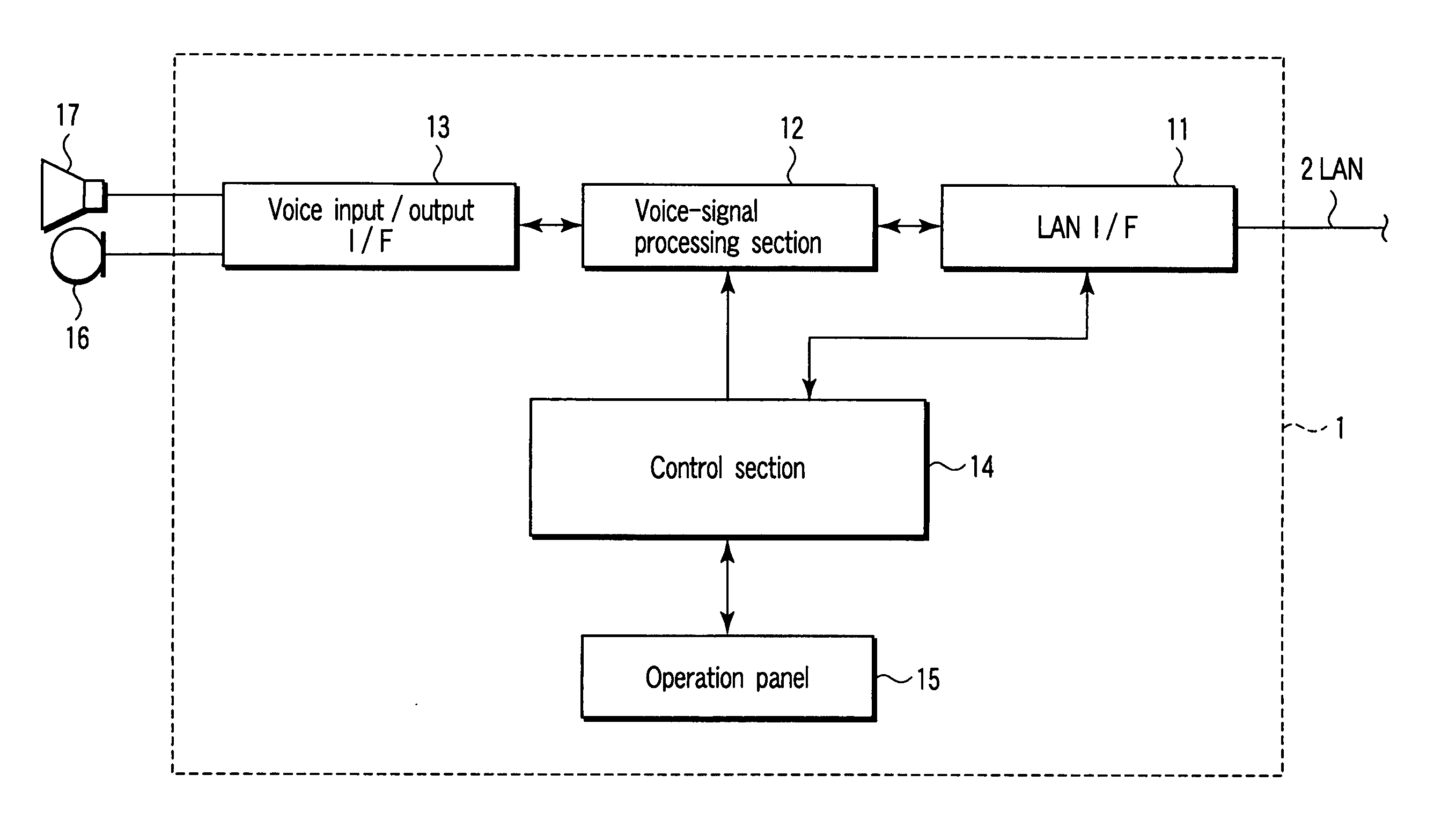
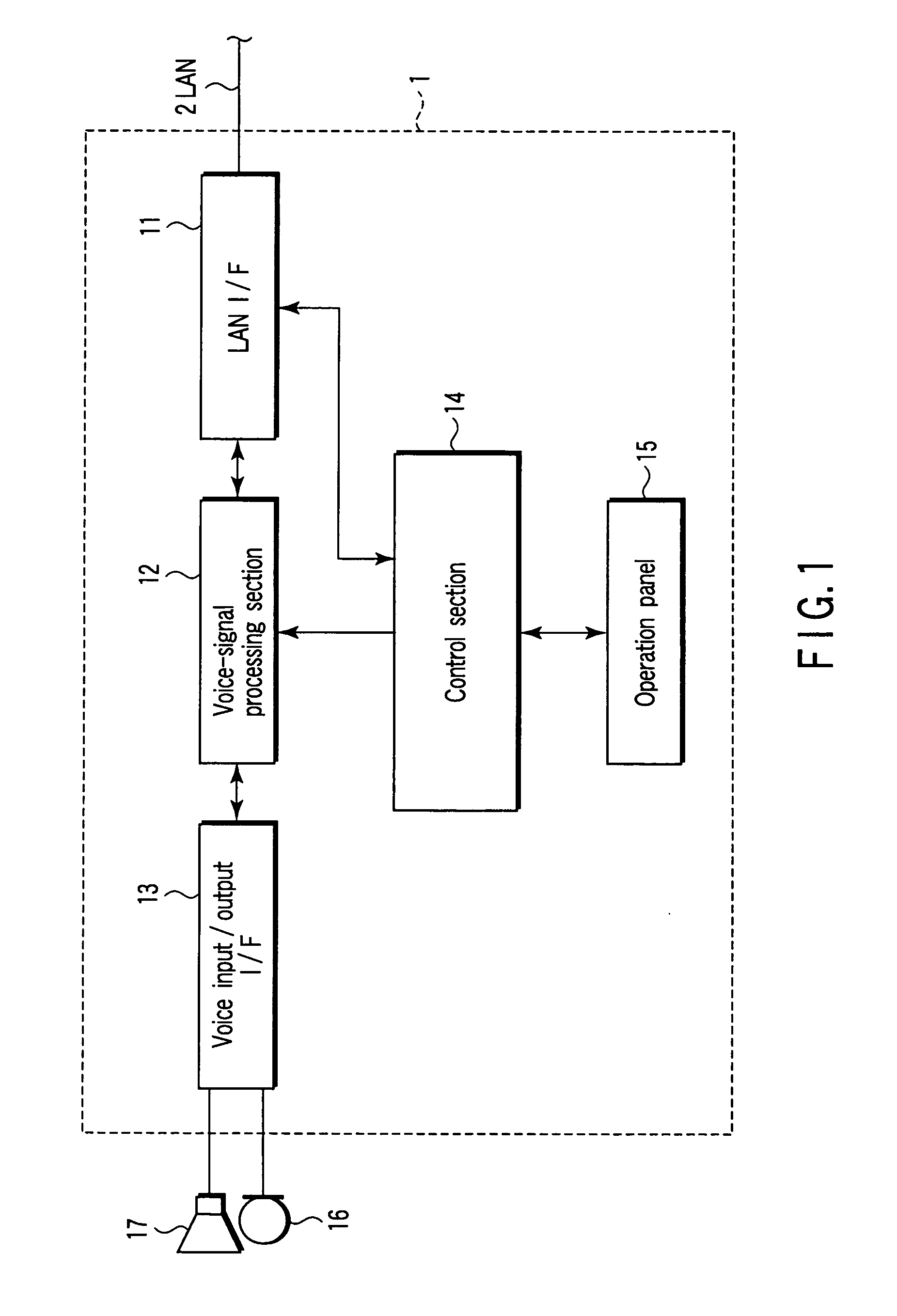
[0032] The first embodiment relates to the processing section 12 and the voice input / output I / F 13 in FIG. 1. The voice input / output I / F 13 includes the voice signal clipping circuit according to the present invention.
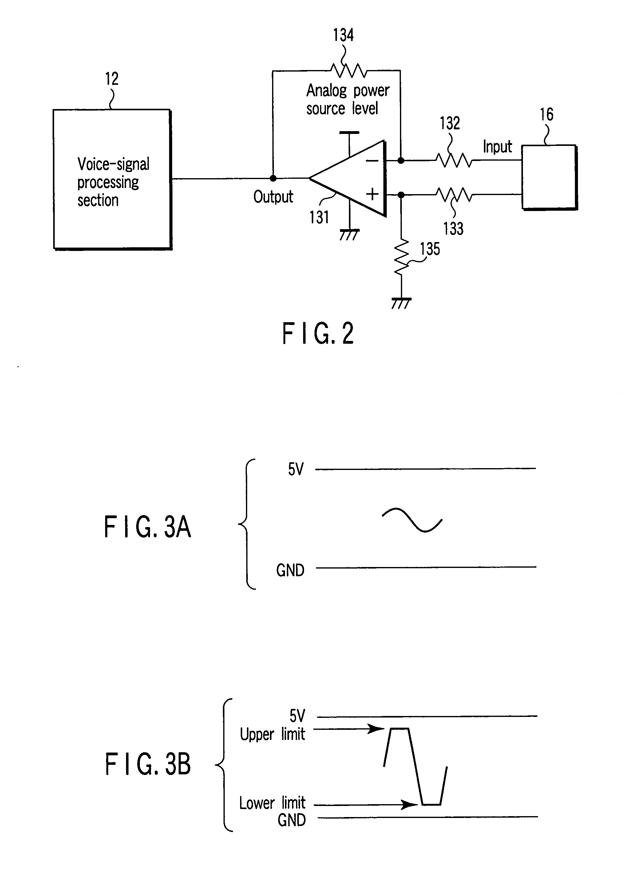
[0033]FIG. 2 is a circuit diagram of a primary configuration of the voice input / output I / F 13 according to the first embodiment.
[0034] The voice input / output I / F 13 includes an operational amplifier 131, and resistors 132, 133, 134, and 135. The resistor 132 lies in a signal line between the microphone 16 and a minus terminal of the operational amplifier 131. The resistor 133 lies in a signal line between the microphone 16 and a plus terminal of the operational amplifier 131.
[0035] The resistor 134 connects between the minus terminal of the operational amplifier 131 and an output terminal of the operational amplifier 131. The resistor 135 connects between the minus terminal of the operational amplifier 131 and a reference potential point.
[0036] The operational ampl...
second embodiment
[0043] The second embodiment relates to the processing section 12 and the voice input / output I / F 13 in FIG. 1.
[0044]FIG. 5 is a circuit diagram of a primary configuration of the voice input / output I / F 13 according to the second embodiment. In FIG. 5, parts same as those in FIG. 2 are designated with like reference numerals, and their detailed explanation will be omitted.
[0045] In the second embodiment, a voltage dividing circuit 21 is provided at an output side of the operational amplifier 131. The voltage dividing circuit 21 has resistors 211 and 212. The resistor 211 lies in a signal line between the operational amplifier 131 and the processing section 12. The resistor 212 connects between an output terminal of the resistor 211 and a reference potential point.
[0046] The voltage dividing circuit 21 receives an output voltage of the operational amplifier 131, and supplies an output of the divided voltage to the processing section 12. Then, a voice signal lower than the input rate...
third embodiment
[0048] The third embodiment relates to the processing section 12 and the voice input / output I / F 13 in FIG. 1.
[0049]FIG. 6 is a circuit diagram of a primary configuration of the voice input / output I / F 13 according to the third embodiment. In FIG. 6, parts same as those in FIG. 2 are designated with like reference numerals, and their detailed explanation will be omitted.
[0050] In the third embodiment, an operational amplifier 31 and resistors 32 and 33 are provided at the latter stage of the operational amplifier 131. The resistor 32 lies in a signal line between a minus terminal of the operational amplifier 31 and an output terminal of the operational amplifier 131. The resistor 33 connects between the minus terminal of the operational amplifier 31 and an output terminal of the operational amplifier 31. A reference voltage is supplied to a plus terminal of the operational amplifier 31.
[0051] The operational amplifier 31 amplifies an output signal from the operational amplifier 131...
PUM
 Abstract
Description
Claims
Application Information