Wavelength selective switching and/or routing system

a selective switching and wavelength technology, applied in the field of optical switching/routing systems, can solve problems such as further complicated problems

Inactive Publication Date: 2005-05-05
AVAGO TECHNOLOGIED FIBER IP SINGAPORE PTE LTD
View PDF7 Cites 9 Cited by
  • Summary
  • Abstract
  • Description
  • Claims
  • Application Information

AI Technical Summary

Problems solved by technology

A common problem encountered in many applications in which high data rate information is modulated on optical carrier beams is the switching of the optical carriers from among an array of channels.
This problem is further complicated in the case of WDM and DWDM systems where many discrete channels are separated by small increments in wavelength.
However from noise, space, and cost perspectives it is more sometimes desirable to directly switch the route of the optical carrier directly from the input channel to the desired channel.

Method used


Image

  • Wavelength selective switching and/or routing system
  • Wavelength selective switching and/or routing system
  • Wavelength selective switching and/or routing system

Examples


embodiment 3

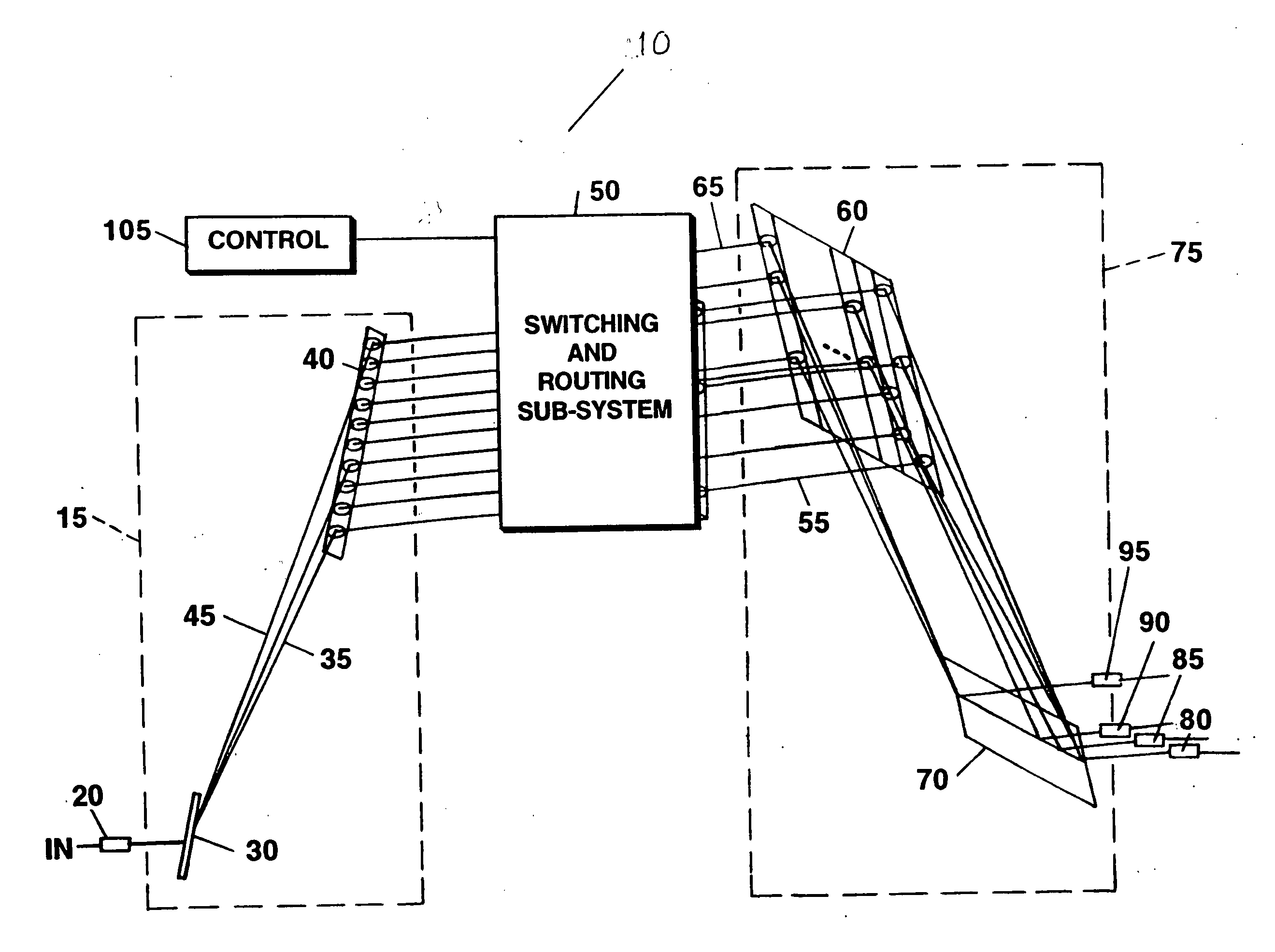
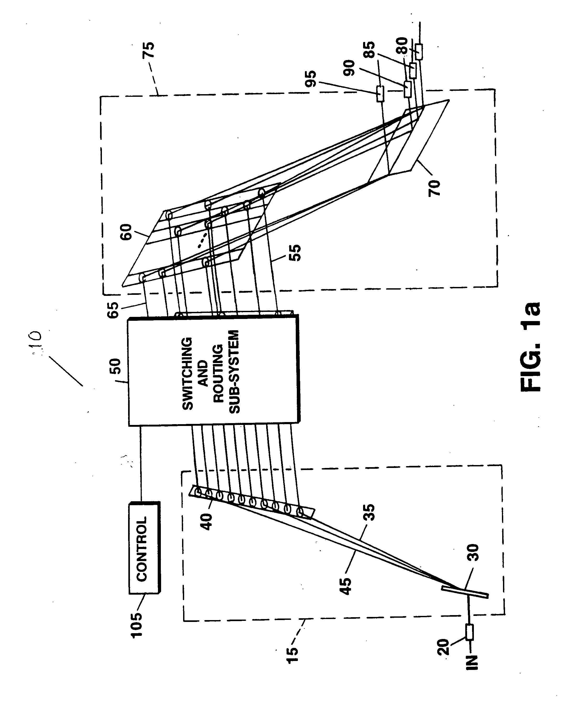
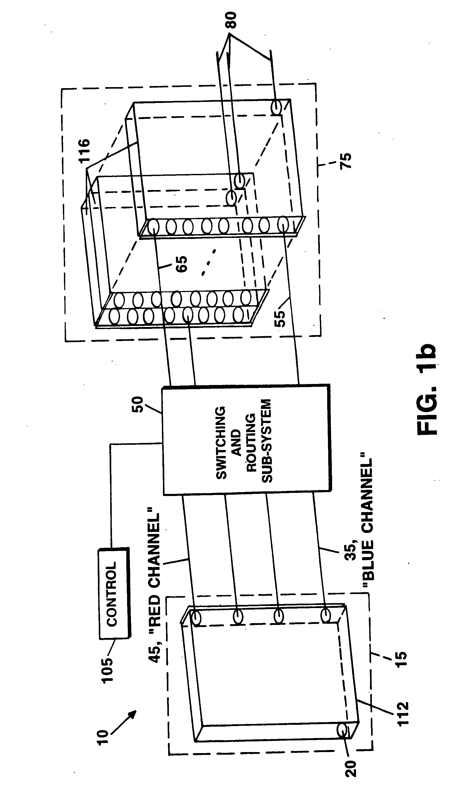
[0041] Referring to FIG. 2a, the input radiation 25 is separated into m spectral input channels 35 through 45 using a twin grating disperser, comprised of gratings 30 and 40, in which the gratings are typically parallel to each other and of the same spatial frequency. (Control means are not shown in FIGS. 2a and 2b. However, the control means operate as in the same manner as in FIG. 1b.) The spectrally resolved input channels are then passed through an array of m 1×N switches 100 as shown. Each of the m input channels 35 through 45 is independently routed to any of N output columns 112 through 114. Output beams 125 through 135 emerge from the switching and routing sub-system 100 and are incident on the recombining sub-system comprised of grating pair 60 and 70. The final grating pair recombiner, comprised of grating pair 60 and 70, is similar to the input grating pair 30 and 40. In the embodiment shown in FIG. 2a, the gratings in the final pair 60 and 70 is wider than the gratings i...

embodiment 600

[0059] The switchable mirror embodiment 600 of the planar switch, also disclosed in U.S. patent application Ser. No. 09 / 943,847 and shown in FIG. 7, would not introduce residual angular or lateral dispersion from the switch. The planar switch 600 makes use of an array 692 of switchable reflection gratings 694 (also referred to as switchable mirrors). The switchable reflection gratings 694 may be, for example, volume holographic diffraction gratings or other switched mirror technology. The switch 600 of FIG. 7 would be a single layer of a stack, shown in cross-section from above. Although three input channels 612 and three output channels 616 are shown, it should be noted that embodiments with other numbers of input and output channels are possible. “Through” or undiffracted output ports 640 may also be useful for some applications.

[0060] Similarly the transmission switch array 700 of FIG. 8 could be used, and would result in an offset. Referring to FIG. 8, transmission switch array ...


PUM


Abstract

Switching and / or routing devices use separating diffraction gratings or AWG, a selectable switching and routing sub-sytem system, and recombining diffraction gratings or AWG to overcomes problems associated with insertion loss, size and compactness, switch isolation, switching speed, which may be present in current optical switching systems. The selectable switching and routing sub-system can include a switchable grating based sub-system or a switchable mirror based sub-sytem.

Description

CROSS-REFERENCE TO RELATED APPLICATIONS [0001] This application is a continuation-in-part of co-pending U.S. patent application Ser. No. 09 / 943,847 filed on Aug. 31, 2001, which is incorporated by reference herein.FIELD OF THE INVENTION [0002] The present invention relates generally to interconnection and switching systems, and, more particularly, to optical switching / routing systems which incorporate the use of selectable switching and routing components. BACKGROUND OF THE INVENTION [0003] With the advent of substantial new uses for high bandwidth digital systems, particularly Wavelength Division Multiplexing (WDM) and Dense Wavelength Division Multiplexing (DWDM) systems, and analog electro-optic systems, there exists a greater need to effectively control the routing and switching capability of electro-optic or optical signals from among many possible paths. This is especially true in digital computing systems where signals must be routed among processors; in analog systems such ...

Claims


Application Information

Patent Timeline
Patent Type & Authority Applications(United States)
IPC IPC(8): G02B6/34
CPCG02B6/12021G02B6/29311G02B6/29395G02B6/29314G02B6/29313
Inventor STONE, THOMAS W.
Owner AVAGO TECHNOLOGIED FIBER IP SINGAPORE PTE LTD
Why Eureka
Try Eureka