
Transfer sheet, method of manufacturing the same and transfer printing method

a technology of transfer sheets and printing methods, applied in the field of transfer sheets, can solve the problems of increased manufacturing costs of printers, increased cost, and inefficient methods of manufacturing conventional transfer sheets, and achieve satisfactory picture quality and high production efficiency

Inactive Publication Date: 2005-05-05
DAI NIPPON PRINTING CO LTD
View PDF36 Cites 0 Cited by
  • Summary
  • Abstract
  • Description
  • Claims
  • Application Information

AI Technical Summary

Benefits of technology

The present invention provides a transfer sheet with a thermal transfer layer having multiple transfer region sets, each with different functions. The transfer sheet also includes identification marks formed in the transfer region sets. The identification marks can be formed using different printing plates or have different forms to create different characteristics. The transfer sheet can be manufactured with high efficiency and can form a satisfactory picture quality. The transfer printing method using the transfer sheet involves recording information in the identification marks, reading them, correcting transfer conditions, and transferring the transfer regions. The technical effects of the invention include improved efficiency in manufacturing and better quality of transferred images.

Problems solved by technology

This method of manufacturing the conventional transfer sheet is not efficient because the transfer layers are printed one by one by using the Y, the M and the C printing cylinder.
Transfer layers of an ink ribbon printed by using a printing cylinder provided with a plurality of transfer layer printing plates differ subtly in thickness from each other because of dimensional errors in the transfer layer printing plates.
However, the above three methods cause the increase of manufacturing costs of printers, because the printers need to be provided with particular mechanisms for detecting the hole, the reflection mark or the bar-code.
In addition, the detection hole and the reflection mark should be changed in accordance with the corresponding ink ribbon, which leads cost increase.

Method used


Image

  • Transfer sheet, method of manufacturing the same and transfer printing method
  • Transfer sheet, method of manufacturing the same and transfer printing method
  • Transfer sheet, method of manufacturing the same and transfer printing method

Examples


first embodiment

Example 1-1

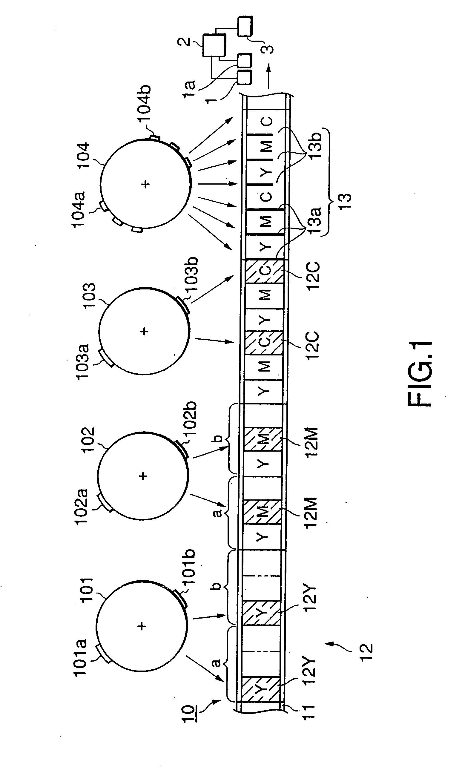
[0049] Referring to FIG. 1 showing a transfer sheet 10 in an example 1-1 of the first embodiment according to the present invention, the transfer sheet 10 comprises a base sheet 11, a thermal transfer layer 12 formed on the base sheet 11, and identification marks 13 (13a and 13b). The thermal transfer layer 12 has a plurality of YMC transfer region sets a and b, each transfer region set a, b having a plurality of thermal transfer regions 12Y, 12M and 12C respectively. The thermal transfer regions 12Y, 12M and 12C have different functions to each other. The identification marks 13 are formed in each of the YMC transfer region sets a and b.

[0050] The base sheet 11 serves as a carrier member of the transfer sheet 10 and may be a sheet having sufficient heat resistance and strength. The base sheet may be a paper sheet, a plastic sheet, such as a PET sheet, or a metal foil of a thickness in the range of 0.5 to 50 μm, preferably, in the range of 3 to 10 μm.

[0051] The thermal...

examples 1-2 and 1-3

[0081] FIGS. 4(A) and 4(B) are plan views of transfer sheets in examples 1-2 and 1-3 of the first embodiment according to the present invention, respectively.

[0082] Referring to FIG. 4(A), a transfer sheet 50A in the example 1-2 has an alternate arrangement of two YMC transfer region sets a and b, each having three transfer regions 52Y, 52M and 52C respectively of different colors (yellow, magenta and cyan). Identification marks 53Ya and 53Y′b are formed in the head transfer regions 52Y of the YMC transfer region sets a and b, respectively.

[0083] The identification marks 53Ya and 53Y′b are the same in form but differ from each other in transmissivity (or reflectivity).

[0084] In the following description, an identification mark designated by a reference character without a dash (′) has a small transmissivity (high optical density), and an identification mark designated by a reference character with a dash (′) has a large transmissivity (low optical density). A photoelectric sensor...

examples 1-4 to 1-7

[0097] FIGS. 5(A) to 5(E) are plan views of transfer sheets in examples 1-4 to 1-7 of the first embodiment according to the present invention.

[0098] In each of the transfer sheets shown in FIGS. 5(A) to 5(E), an identification mark formed in the head transfer region of each YMC transfer region set is two lines, and identification marks formed in the other transfer regions of the same YMC transfer region set are a single line.

[0099] In a transfer sheet 60A in the example 1-4 shown in FIG. 5(A), identification marks 63YYa and 63Y′Y′b formed respectively in the respective head transfer regions of YMC transfer region sets a and b are different from each other in transmissivity.

[0100] Each of the Y printing cylinder 101, the M printing cylinder, the C printing cylinder 103 and the mark printing cylinder 104 is provided with three printing plates when forming the transfer regions and the identification marks of a transfer sheet 60B in the example 1-5 shown in FIG. 5(B). An arrangement ...


PUM

PropertyMeasurementUnit
thicknessaaaaaaaaaa
thicknessaaaaaaaaaa
thicknessaaaaaaaaaa

Abstract

A transfer sheet comprises a base sheet, a thermal transfer layer having a plurality of YMC transfer region sets, each transfer region set having a plurality of transfer regions with functions different from each other, and identification marks formed in the YMC transfer region sets, respectively. The identification marks formed in the different YMC transfer region sets have different forms, respectively. The transfer regions are printed by using a plurality of transfer region printing cylinders, each provided with a plurality of printing plates, and the identification marks of different forms are printed by using a single identification mark printing cylinder. The respective identification marks of the YMC transfer region sets represent information about the positions of the corresponding YMC transfer region sets, respectively. The transfer regions are transferred after correcting transfer conditions on the basis of information represented by the identification marks.

Description

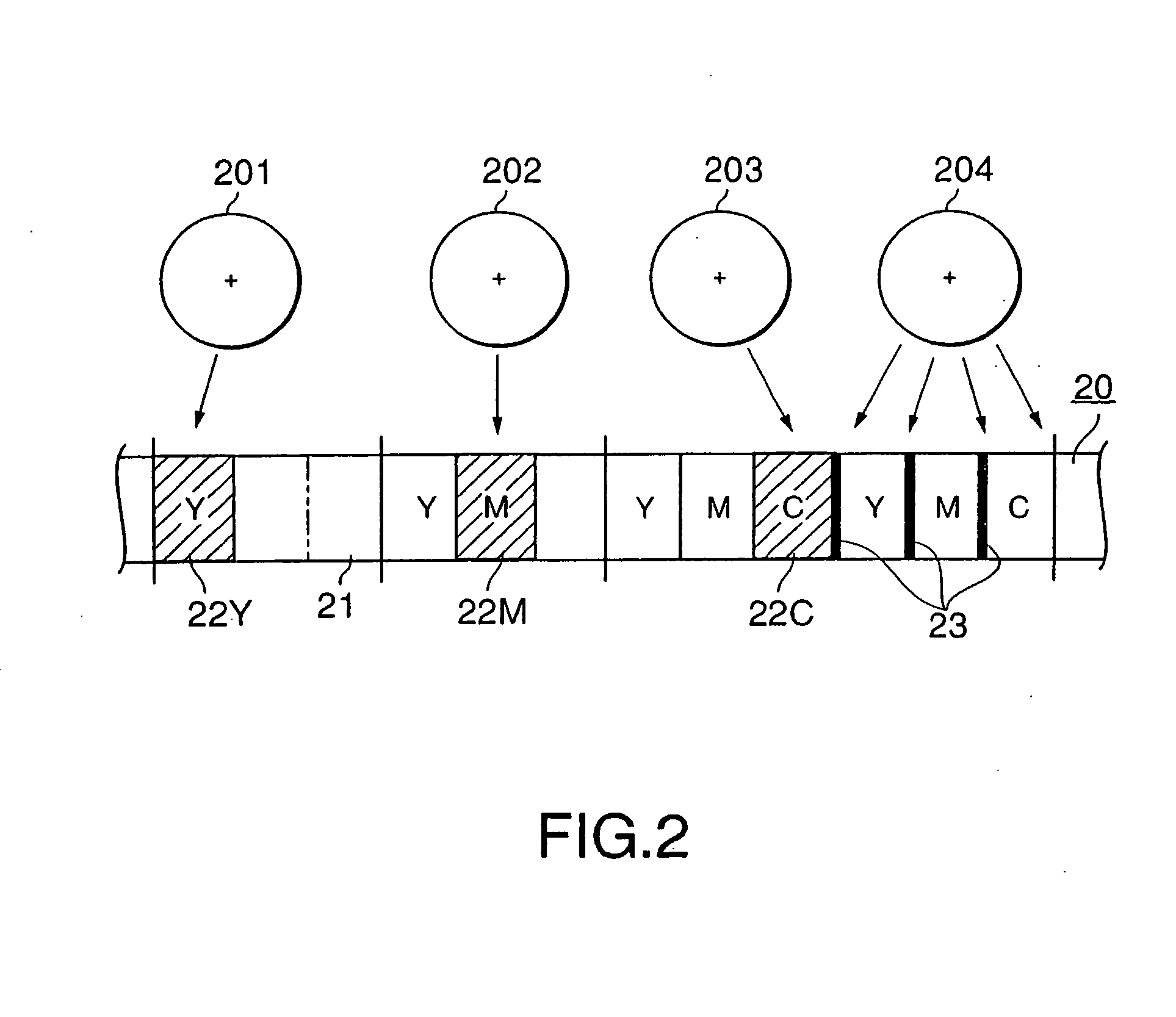
BACKGROUND OF THE INVENTION [0001] 1. Field of the Invention [0002] The present invention relates to a transfer sheet suitable for making ink ribbons for transfer printers, a method of manufacturing the same, and a transfer printing method. [0003] 2. Description of the Related Art [0004]FIG. 2 is a typical view of assistance in explaining a conventional transfer sheet and a method of manufacturing the same. [0005] A conventional transfer sheet 20 in the form of an ink ribbon (JP-B No. 6-96307) by way of example comprises a ribbon (base sheet) 21, a plurality of ink regions each of a plurality of color ink regions (yellow, magenta and cyan ink regions), (thermal transfer layers) 22 (22Y, 22M, 22C), and color lines (identification marks) 23 of colors of the color ink regions 22, extending perpendicularly to the length of the ink ribbon. [0006] The transfer sheet 20 is manufactured by a suitable method, such as a gravure printing method, using printing cylinders 201, 202, 203 and 204 e...

Claims


Application Information

Patent Timeline
Patent Type & Authority Applications(United States)
IPC IPC(8): B41M5/34B41M5/382B41M5/385
CPCB41M5/345Y10T428/24942B41M5/38207
Inventor SAITO, HITOSHI
Owner DAI NIPPON PRINTING CO LTD
Learn More