

Duo-display mobile phone
a mobile phone and display technology, applied in the field of dual-display mobile phones, can solve the problems of unable to simultaneously perform multiple tasks with such mobile phones, and unable to meet the requirements of the task at hand,
- Summary
- Abstract
- Description
- Claims
- Application Information
AI Technical Summary
Benefits of technology
Problems solved by technology
Method used
Image

Examples
first embodiment
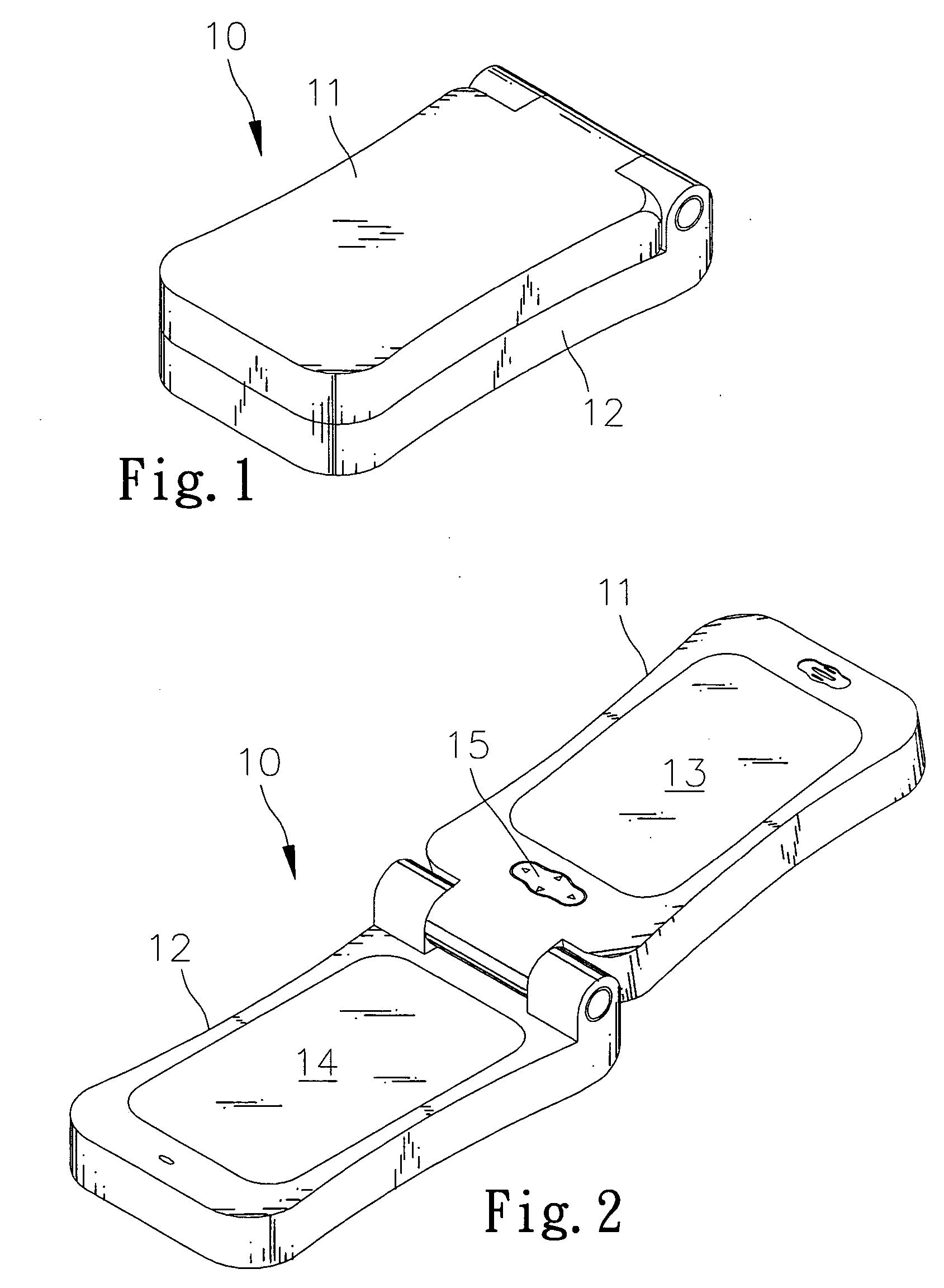
[0022]FIGS. 1 and 2 show a duo-display mobile phone 10 according to the present invention. The duo-display mobile phone 10 includes a first unit 11, a second unit 12 pivotally connected with the first unit 11, a first display 13 installed at the first unit 11, a second display 14 installed at the second unit 12 and a four-way button 15 installed at the first unit 11.
[0023] The duo-display mobile phone 10 can be pivoted between a first position shown in FIG. 1 and a second position shown in FIG. 2. In the first position, the first unit 11 and the second unit 12 cover each other, i.e., the first display 13 and the second display 14 cannot be observed and the four-way button 15 cannot be operated. In the second position, the first unit 11 and the second unit 12 do not cover each other, i.e., the first display 13 and the second display 14 can be observed and the four-way button 15 can be operated.
[0024] The first display 13 is used to show signal condition, battery capacity, time, back...
second embodiment
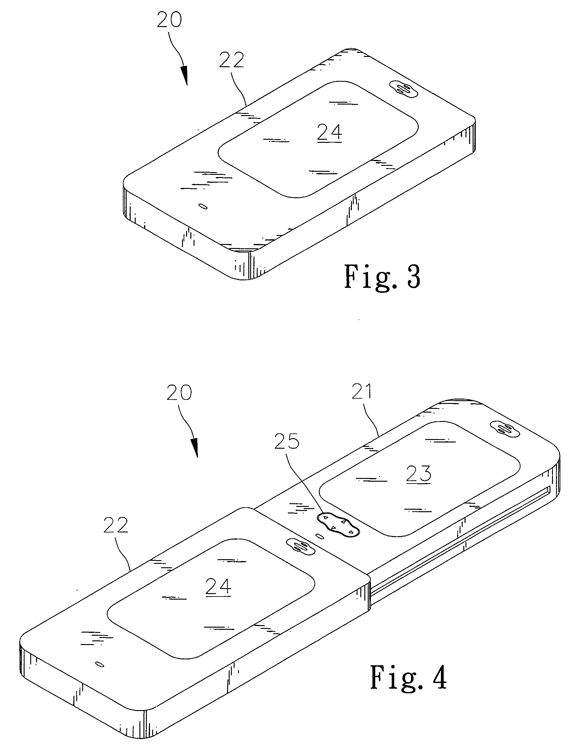
[0026]FIGS. 3 and 4 show a duo-display mobile phone 20 according to the present invention. The duo-display phone 20 includes a first unit 21, a second unit 22 movably mounted on the first unit 21, a first display 23 installed at the first unit 21, a second display 24 installed at the second unit 22 and a four-way button 25 installed at the first unit 21.
[0027] The second unit 22 is configured as a sliding cover for the first unit 21. The second unit 22 can be moved relative to the first unit 21 between a first position shown in FIG. 3 and a second position shown in FIG. 4. In the first position, the first unit 21 is covered by means of the second unit 22. Thus, the first display 23 cannot be observed and the four-way button 25 cannot be operated. In the second position, the first unit 21 is not covered by means of the second unit 22. Thus, the first display 23 can be observed and the four-way button 25 can be operated. The second embodiment is otherwise identical to the first embodi...
third embodiment
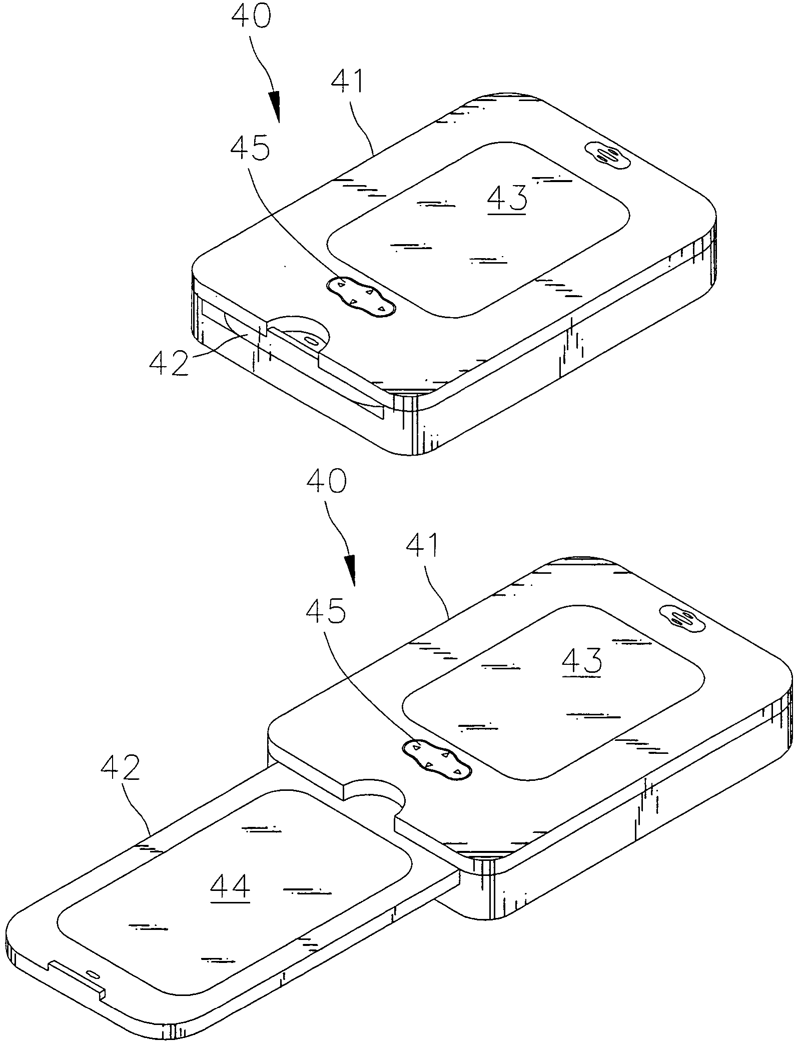
[0028]FIGS. 5 and 6 show a duo-display mobile phone 30 according to the present invention. The duo-display phone 30 includes a first unit 31, a second unit 32 that can be inserted into a space defined in the first unit 31, a first display 33 installed at the first unit 31, a second display 34 installed at the second unit 32 and a four-way button 35 installed at the first unit 31.
[0029] The second unit 32 is movable relative to the first unit 31 in a transverse direction. The second unit 32 is movable relative to the first unit 31 between a first position shown in FIG. 5 and a second position shown in FIG. 6. In the first position, the first unit 31 covers the second unit 32. Thus, the second display 34 cannot be observed. In the second position, the first unit 31 does not cover the second unit 32. Thus, the second display 34 can be observed. The third embodiment is otherwise identical to the first embodiment and therefore will not further be described in detail.
PUM
 Abstract
Description
Claims
Application Information