
Composite system of scanning electron microscope and focused ion beam

a scanning electron microscope and focused ion beam technology, applied in the field of composite systems of scanning electron microscopes and focused ion beams, can solve the problems of noise, small foreign matter or abnormal shape is overlooked, secondary electron involved in fib irradiation is mixed in a detection signal, etc., to achieve accurate adjustment of signal level and remove noise components

Active Publication Date: 2006-12-26
HITACHI HIGH TECH SCI CORP
View PDF1 Cites 16 Cited by
  • Summary
  • Abstract
  • Description
  • Claims
  • Application Information

AI Technical Summary

Benefits of technology

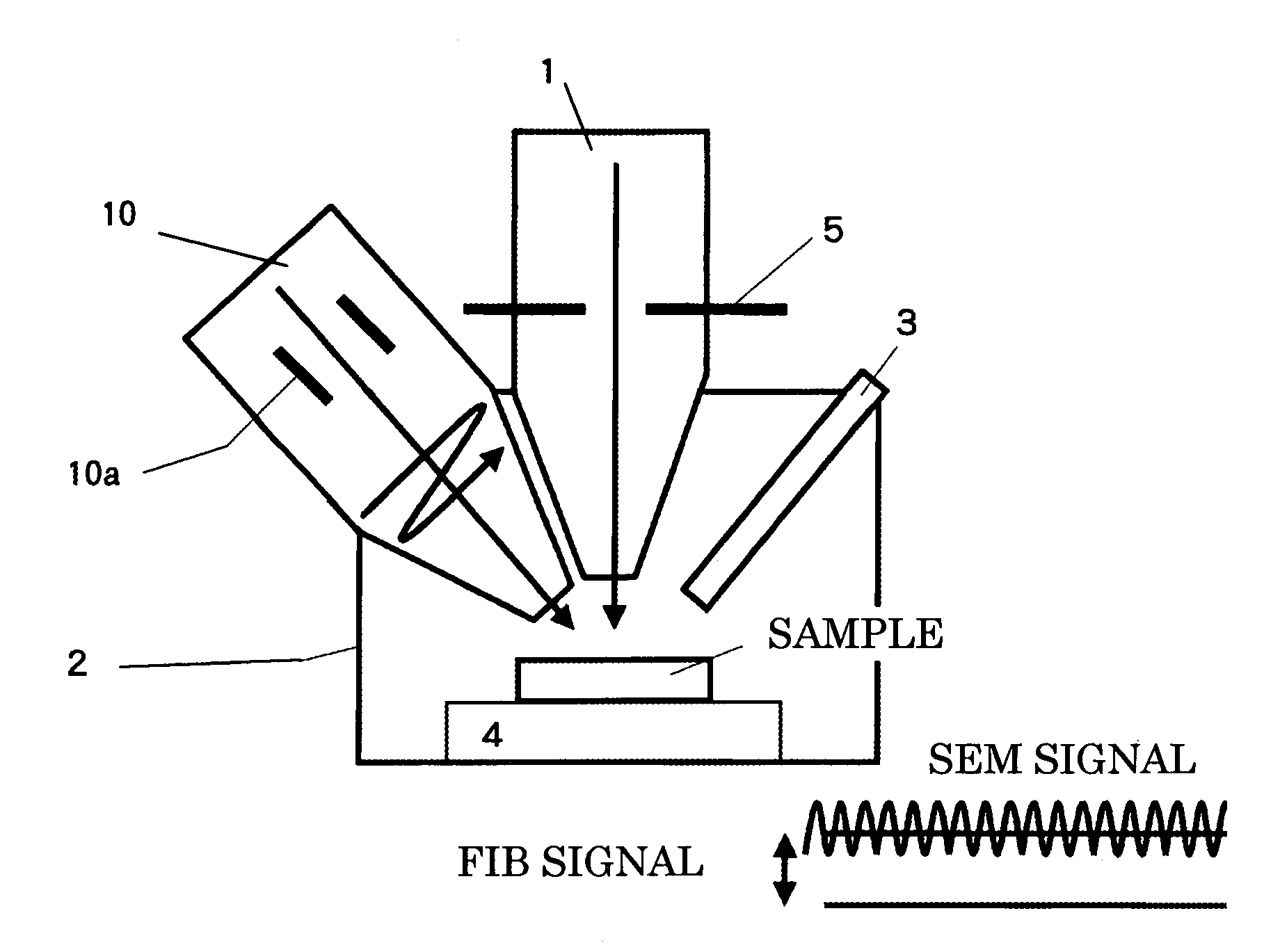
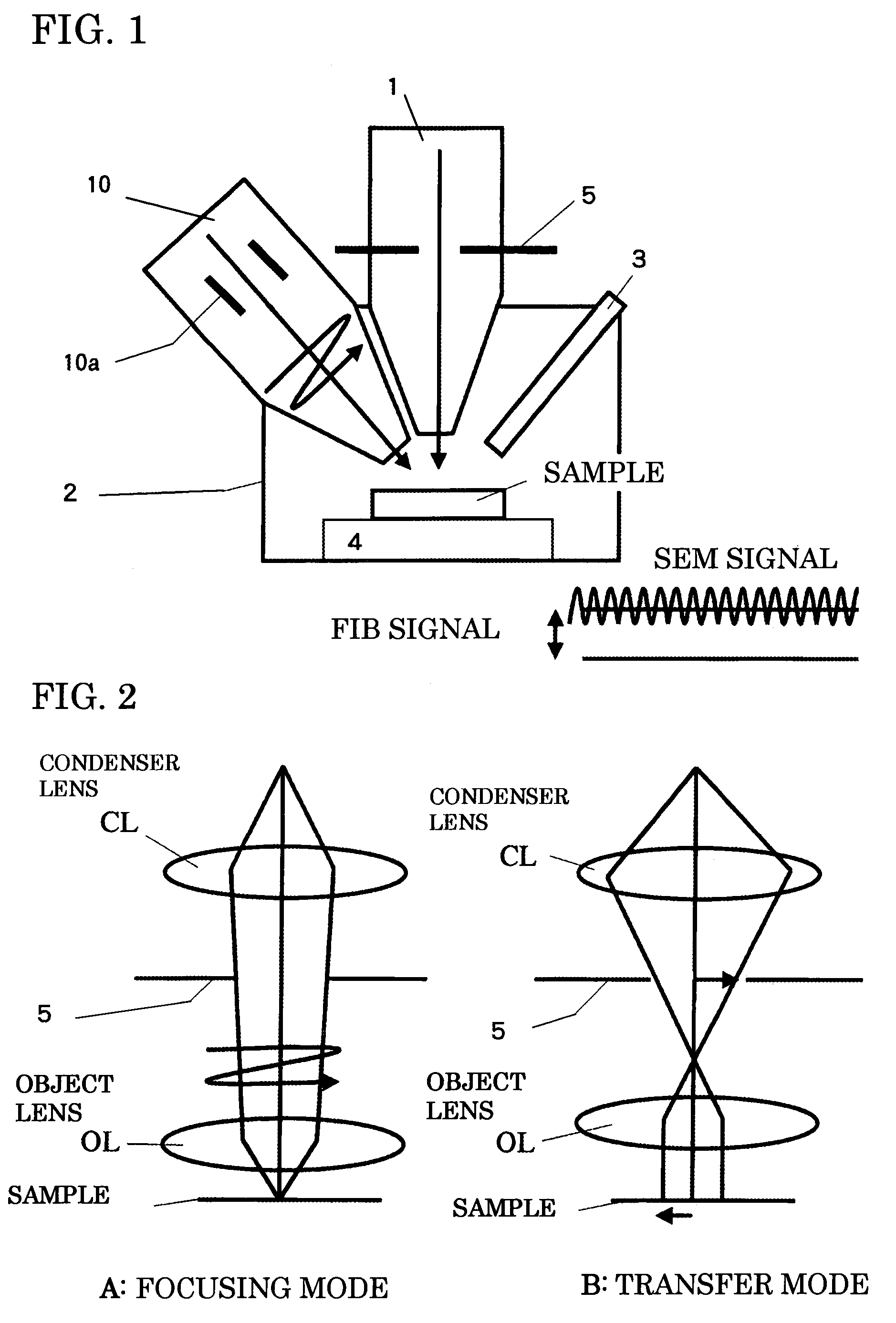
The invention is a complex apparatus and method for ion beam machining that includes an FIB lens-barrel and an SEM lens-barrel. The apparatus has a slit with a machining shape in the aperture of the FIB lens-barrel, which allows for ion beam machining instead of scanning using a focused ion beam. The apparatus can switch between focusing mode and transfer mode to perform various machining tasks by selecting or combining multiple machining patterns. The method includes detecting the machining position using a scanning electron microscope image and transferring the pattern to the detected position using ion beam irradiation. The complex apparatus and method improve stability and efficiency of the machining process. Additionally, a protective film can be formed using electron beam chemical vapor deposition to prevent damage to the sample. The invention also includes a secondary electron detector with an electric filter to remove noise components from the detected SEM signal.

Problems solved by technology

However, in this case, work of machining and observing a state of the machining has to be carried out repeatedly.
For example, a section machining observation apparatus described in JP-A-2-123749 has an object of solving problems in that operation is troublesome because the apparatus has to be moved between a machining angle (usually, horizontal) and an observation angle (about 45 to60 degrees) several times, mechanical error involved in movement of a sample occurs, and it is likely that a very small foreign matter or an abnormal shape is overlooked because a section cannot be seen during machining.
However, when it is attempted to perform a cross-section observation with the SEM simultaneously during machining by the FIB, a secondary electron involved in the FIB irradiation is mixed in an SEM detection signal and becomes noise.

Method used


Image

  • Composite system of scanning electron microscope and focused ion beam
  • Composite system of scanning electron microscope and focused ion beam
  • Composite system of scanning electron microscope and focused ion beam

Examples


first embodiment

[First Embodiment]

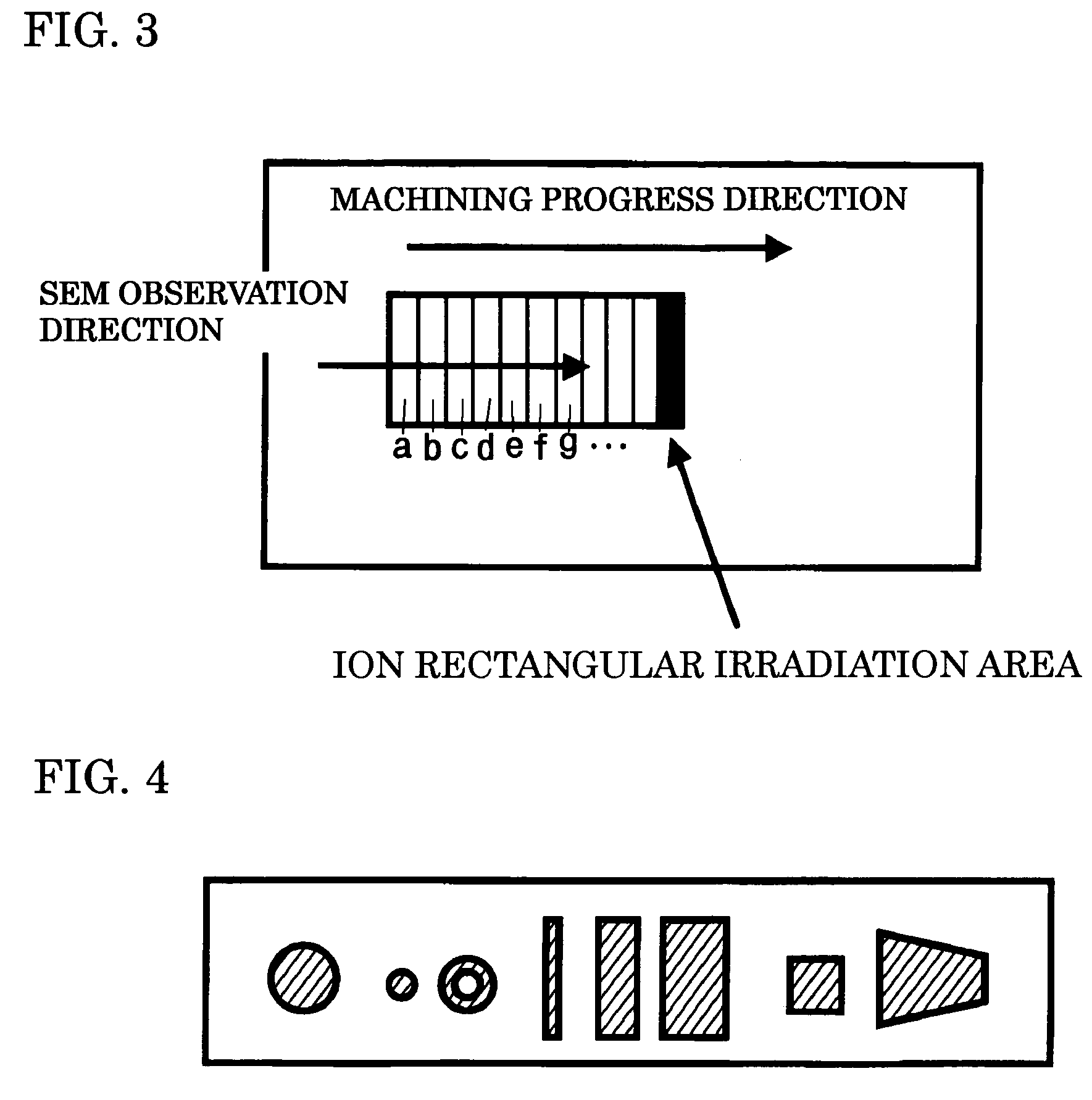
[0038]FIG. 4 shows an embodiment of an aperture that is used in the complex apparatus of the invention. In the embodiment shown here, opening patterns are a large circle, a small circle, a ring, rectangles with small, medium, and large widths, a square, and a trapezoid. It is needless to mention that patterns are not limited to these and can be created appropriately. In use, when a pattern matches a machining area, the pattern only has to be selected and used. Alternatively, it is also possible to combine several patterns to create a necessary machining pattern. In the latter case, patterns to be combined only have to be selected in order to carry out machining. All the cases are the same in that an area is uniformly irradiated by an FIB rather than scanning the area with the FIB to form a machining pattern. Thus, the FIB simply becomes a uniform background noise for an SEM signal in the machining area,

second embodiment

[Second Embodiment]

[0039]Next, FIG. 5 shows an embodiment including means for removing a uniform background noise due to ion beam irradiation from an SEM signal in which the background noise is detected. In view of the fact that this background noise is superimposed on the SEM signal as a bias component corresponding to a beam current of an FIB, the inventors have achieved an idea of detecting the beam current of the FIB and correct the beam current. For this beam current detection, it is advantageous to arrange the aperture 5 of a transfer pattern determining a machining are a between the object lens OL and a sample surface in a mask form. By forming this mask with a conductive material, it is possible to use the aperture 5 also as a beam current detector. In other words, as shown in FIG. 5, the aperture 5 arranged in the mask form between the object lens OL, which is arranged on a tip side of the FIB lens-barrel 1, and the sample surface is used as a detection electrode to pick up...

third embodiment

[Third Embodiment]

[0041]Next, FIG. 7 shows another embodiment including means for removing a uniform background noise due to ion beam irradiation from an SEM signal in which the background noise is detected. In the embodiment described above, a beam current of an FIB, which causes this background noise, is detected and corrected. However, in this embodiment, in view of the fact that a beam current of an FIB is measured in advance and can be allocated to setting conditions for a lens optical system of an FIB apparatus, the inventors have achieved an idea of performing level adjustment based on the setting conditions for the lens optical system without measuring a beam current directly. As shown in FIG. 7, in this embodiment, it is unnecessary to provide a special component. A beam current is calculated from the setting conditions for the lens optical system in a controller and a background noise level based on this beam current is further calculated to perform correction for the back...


PUM


Abstract

A composite system of a scanning electron microscope (SEM) and a focused ion beam apparatus (FIB) has an FIB lens barrel for irradiating a focused ion beam to an irradiating position on a sample surface and an SEM lens barrel for observing a machining state of the machined sample surface. The FIB lens barrel has an aperture defining at least one slit of a preselected pattern so that during irradiation of the sample surface with the focused ion beam, the aperture is irradiated by the focused ion beam with a width covering the slit to thereby machine the sample surface in the form of the preselected pattern of the slit.

Description

BACKGROUND OF THE INVENTION[0001]1. Field of the Invention[0002]The present invention relates to a composite system (hereinafter “complex apparatus” that can observe a sample with a scanning electron microscope (SEM) on a real time basis while machining the sample with a focused ion beam apparatus (FIB).[0003]2. Background Information[0004]There has already been publicly known a so-called complex FIB system that is provided with an electron lens-barrel separately to have an observation function by an SEM in order to observe a machining state of a sample in applying etching and CVD to the sample with an FIB apparatus. In addition to functions for performing the etching and the CVD, the FIB apparatus includes a function as an ion microscope for detecting a secondary charged particle such as an electron or an ion emitted from a sample surface by ion irradiation and forming an amount of the detection as an image in association with an irradiation position. In response to needs for an ob...

Claims


Application Information

Patent Timeline
Patent Type & Authority Patents(United States)
IPC IPC(8): H01L21/66H01J37/305H01L21/00H01J37/28H01J37/317
CPCH01J37/28H01J37/3056H01L22/26H01J2237/31749
Inventor OI, MASAMICHIOGAWA, TAKASHI
Owner HITACHI HIGH TECH SCI CORP
Learn More