
Electronic device

a technology of electronic devices and wiring widths, applied in the direction of printing, printing, printing, etc., can solve the problems of increasing the number of terminals, difficulty in securing a sufficient wiring interval and a wiring width, and increasing the degree of freedom of wiring layou

Active Publication Date: 2016-09-22
SEIKO EPSON CORP
View PDF3 Cites 13 Cited by
  • Summary
  • Abstract
  • Description
  • Claims
  • Application Information

AI Technical Summary

Benefits of technology

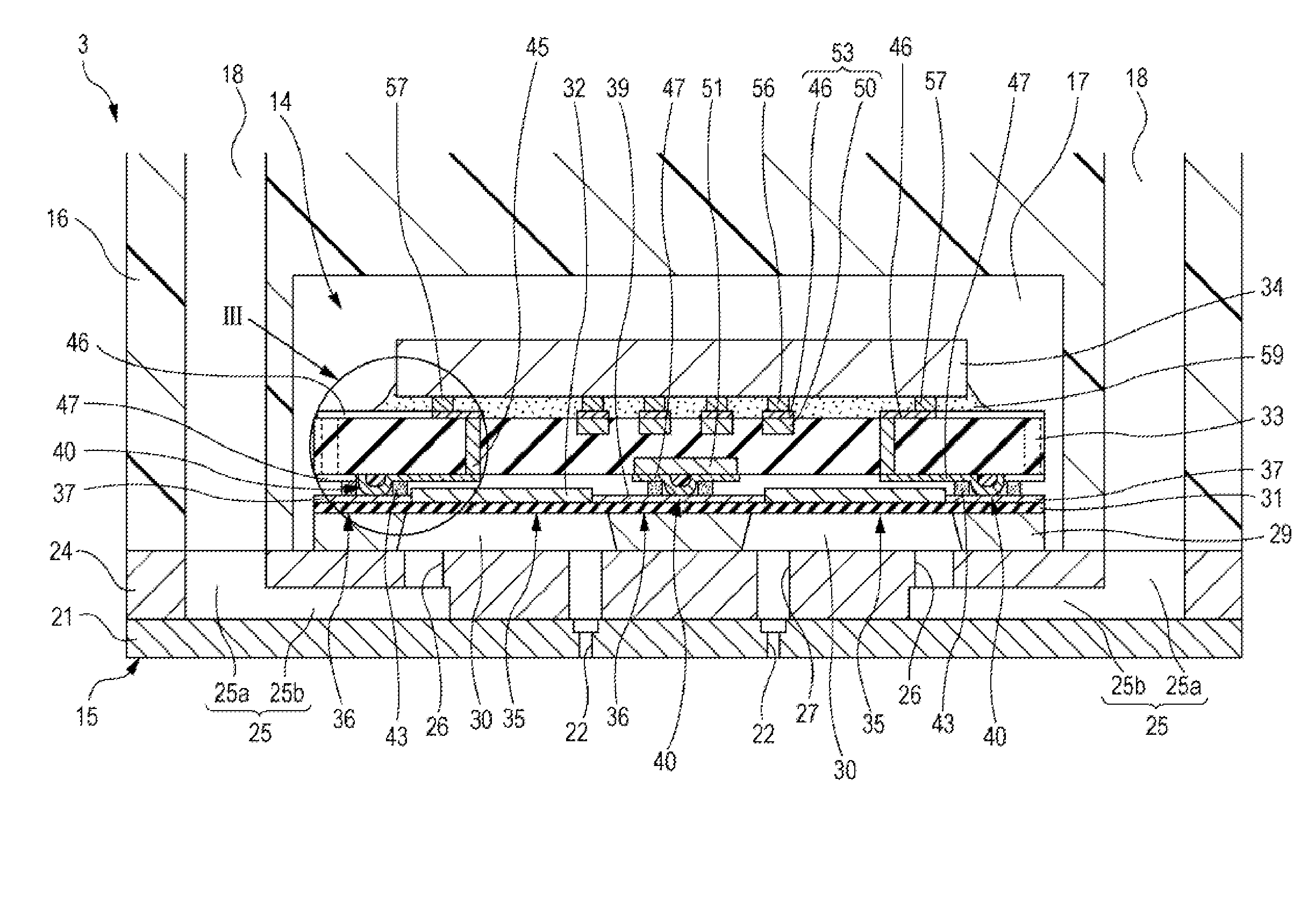
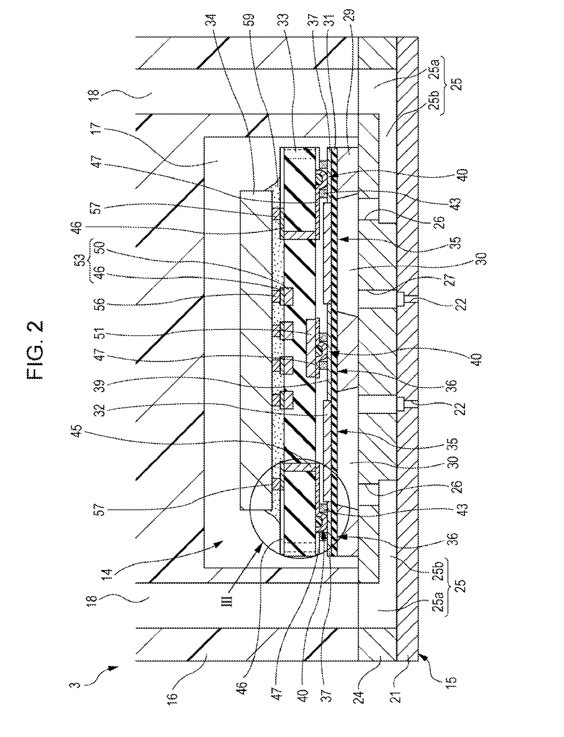
The invention provides an electronic device that can be made smaller. This is achieved by designing a wiring substrate that allows for separate pitch conversion on both surfaces, thus reducing the space between terminals and wires. The use of elasticity in the second terminal further improves reliability and ease of manufacturing. Additionally, the degree of freedom of wiring layout is increased by relaying the first and second surfaces at a certain position on the wiring substrate.

Problems solved by technology

However, with an increase in the number of nozzles and a high density of nozzles, the number of terminals increases, and if the terminal pitch is narrowed, it is difficult to perform the pitch conversion without changing an interval between one terminal and the other terminal.
In other words, as a wiring is positioned closer to the outside, among arranged wirings, the wiring has a steeper inclination relative to the arrangement direction of the terminal, and has difficulty in securing a sufficient wiring interval and a wiring width.
If increasing the interval between the terminal on the drive IC side and the terminal on the piezoelectric element side in order to secure the wiring interval and the wiring width, the sizes of the sealing plate and the drive IC are increased, and as a result, it is difficult to miniaturize the electronic device.

Method used


Image

  • Electronic device
  • Electronic device
  • Electronic device

Examples


Embodiment Construction

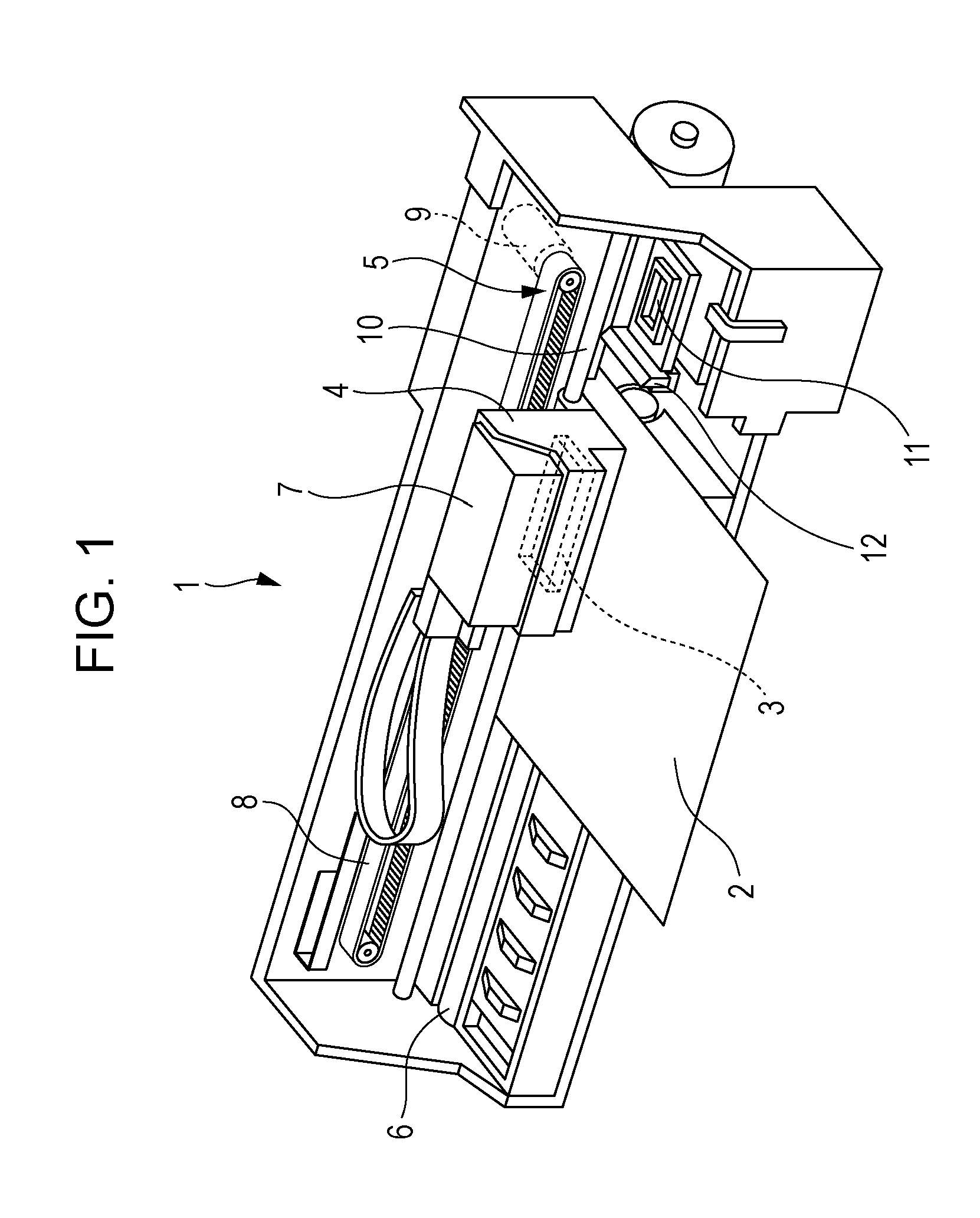
[0027]Hereinafter, embodiments of the present invention will be described with reference to the accompanying drawings. Note that in the embodiments described below, various limits are presented as preferred specific embodiments of the invention, but the scope of the present invention is not limited to these embodiments, unless a particular description for limiting the invention is given in the following description. Further, in the following description, an ink jet printer (hereinafter, referred to as a printer) which is a type of a liquid ejecting apparatus equipped with an ink jet recording head (hereinafter, referred to as a recording head) which is a type of a liquid ejecting head provided with an electronic device according to the present invention will be described as an example.

[0028]The configuration of the printer 1 will be described with reference to FIG. 1. The printer 1 is an apparatus that records an image or the like by ejecting ink (a type of liquid) onto the surface ...


PUM


Abstract

An electronic device includes a sealing plate including a first surface connected to a pressure chamber formation substrate, and a second surface having a drive IC provided thereon. The sealing plate includes a first region in which a plurality of individual connection terminals are arranged, and a second region in a position different from the first region. A plurality of bump electrodes are arranged at a pitch different from a pitch of an individual connection terminals, in a region overlapping a second region, and a wiring group connecting the individual connection terminal and a bump electrode includes a first wiring of which a position of a pass-through wiring relaying the first surface and the second surface is within the first region. A second wiring of which a position of a pass-through wiring connecting the first surface and the second surface is within the second region.

Description

BACKGROUND[0001]1. Technical Field[0002]The present invention relates to an electronic device provided with a wiring substrate having wirings formed thereon.[0003]2. Related Art[0004]An electronic device includes a drive element such as a piezoelectric element to be deformed in response to an applied voltage, and the electronic device is applied to various types of devices, sensors, or the like. For example, a liquid ejecting apparatus ejects various types of liquid from a liquid ejecting head using the electronic device. Examples of the liquid ejecting apparatus include an image recording apparatus such as an ink jet printer and an ink jet plotter, but in recent years, the liquid ejecting apparatus has also been applied to various manufacturing apparatuses, by taking advantage of features that a very small amount of liquid can be accurately landed at a predetermined position. For example, the liquid ejecting apparatus has been applied to a display manufacturing apparatus that manuf...

Claims


Application Information

Patent Timeline
IPC IPC(8): H01L41/047H05K1/02B41J2/14H05K1/11
CPCH01L41/0475H05K1/11H05K2201/10083B41J2/14201H05K1/0284B41J2/045B41J2002/14491B41J2202/18H10N30/875
Inventor TANAKA, SHUICHI
Owner SEIKO EPSON CORP
Learn More