Voice code conversion method and apparatus

a voice code and voice technology, applied in the field of voice code conversion methods and apparatuses, can solve the problems of increasing delay, unable to communicate between a cellular telephone network and the internet, and pronounced decline in the quality of reconstructed speech

Inactive Publication Date: 2009-09-15
FUJITSU LTD
View PDF7 Cites 15 Cited by
  • Summary
  • Abstract
  • Description
  • Claims
  • Application Information

AI Technical Summary

Benefits of technology

[0078]Accordingly, an object of the present invention is to make it possible to perform a voice code conversion even between voice encoding schemes having different subframe lengths.

Problems solved by technology

However, communication between a cellular telephone network and the Internet cannot take place if a voice encoding scheme used by the cellular telephone network and a voice encoding scheme used by the Internet differ.
Problems arise as a consequence, namely a pronounced decline in the quality of reconstructed speech and an increase in delay.
Hence the sound quality of the reconstructed speech is much poorer than that of the original sound.
When use is made of a tandem connection in which encoding and decoding are repeated, the quality of reconstructed speed undergoes a market decline.
Consequently, the voice code thus obtained is not necessarily the best.
However, when the re-encoding is performed according to this method, certain problems arise, namely pre-reading (i.e., delay) of signals owing to LPC analysis and pitch analysis, and a major decline in sound quality.
With voice code conversion according to prior art 2, a conversion to voice code is made on the assumption that subframe length in encoding scheme 1 and subframe length in encoding scheme 2 are equal, and therefore a problem arises in code conversion in a case where the subframe lengths of the two encoding schemes differ.
That is, since the algebraic codebook is such that pulse position candidates are decided in accordance with subframe length, pulse positions are completely different between schemes (G.729A and EVRC) having different subframe lengths, and it is difficult to make pulse positions correspond on a one-to-one basis.

Method used


Image

  • Voice code conversion method and apparatus
  • Voice code conversion method and apparatus
  • Voice code conversion method and apparatus

Examples


first embodiment

(B) First Embodiment

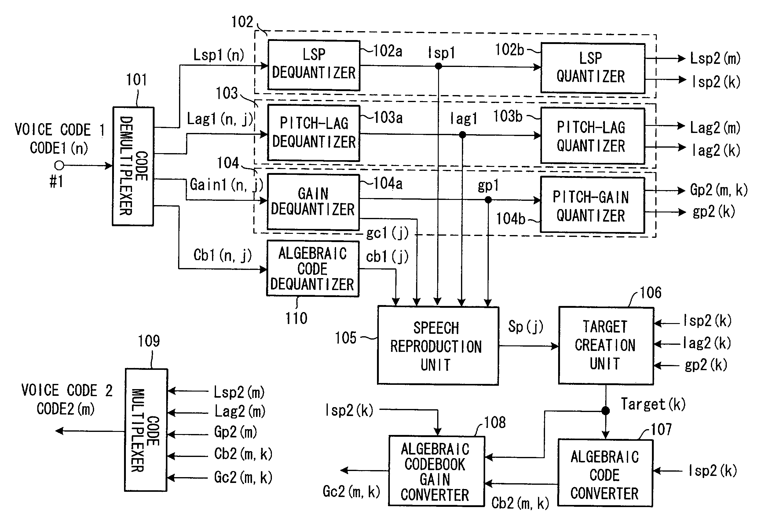
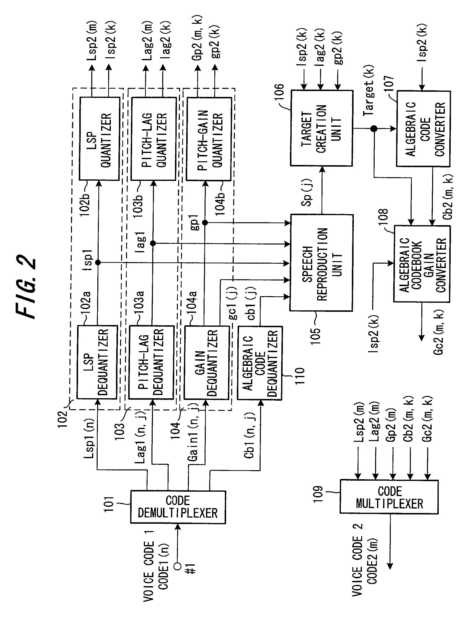
[0119]FIG. 2 is a block diagram of a voice code conversion apparatus according to a first embodiment of the present invention. Components in FIG. 2 identical with those shown in FIG. 1 are designated by like reference characters. This embodiment illustrates a case where G.729A is used as voice encoding scheme 1 and EVRC as voice encoding scheme 2. Further, though three modes, namely full-rate, half-rate and ⅛-rate modes are available in EVRC, here it will be assumed that only the full-rate mode is used.

[0120]Since frame length is 10 ms in G.729A and 20 ms in EVRC, two frames of voice code in G.729A is converted one frame of voice code in EVRC. A case will now be described in which voice code of an nth frame and (n+1)th frame of G.729A shown in (a) of FIG. 3 is converted to voice code of an mth frame in EVRC shown in (b) of FIG. 3.

[0121]In FIG. 2, an nth frame of voice code (channel data) CODE1(n) is input from a G.729A-compliant encoder (not shown) to a terminal ...

second embodiment

(C) Second Embodiment

[0140]FIG. 9 is a block diagram of a voice code conversion apparatus according to a second embodiment of the present invention. Components in FIG. 9 identical with those of the first embodiment shown in FIG. 2 are designated by like reference characters. The second embodiment differs from the first embodiment in that ① the algebraic codebook gain converter 108 of the first embodiment is deleted and substituted by an algebraic codebook gain quantizer 111, and ② the algebraic codebook gain code also is converted in the quantization parameter region in addition to the LSP code, pitch-lag code and pitch-gain code.

[0141]In the second embodiment, only the method of converting the algebraic codebook gain code differs from that of the first embodiment. The method of converting the algebraic codebook gain code according to the second embodiment will now be described.

[0142]In G.729A, algebraic codebook gain is quantized ever 5-ms subframe. If 20 ms is considered as the un...

third embodiment

(D) Third Embodiment

[0145]FIG. 11 is a block diagram of a voice code conversion apparatus according to a third embodiment of the present invention. The third embodiment illustrates an example of a case where EVRC voice code is converted to G.729A voice code. In FIG. 11, voice code is input to a rate discrimination unit 201 from an EVRC encoder, whereupon the rate discrimination unit 201 discriminates the EVRC rate. Since rate information indicative of the full rate, half rate or ⅛ rate is contained in the EVRC voice code, the rate discrimination unit 201 uses this information to discriminate the EVRC rate. The rate discrimination unit 201 changes over switches S1, S2 in accordance with the rate, inputs the EVRC voice code selectively to prescribed voice code converters 202, 203, 204 for full-, half- and eight-rates, respectively, and sends G.729A voice code, which is output from these voice code converters, to the side of a G.729A decoder.

[0146]Voice Code Converter for Full Rate

[014...


PUM


Abstract

It is so arranged that a voice code can be converted even between voice encoding schemes having different subframe lengths. A voice code conversion apparatus demultiplexes a plurality of code components (Lsp1, Lag1, Gain1, Cb1), which are necessary to reconstruct a voice signal, from voice code in a first voice encoding scheme, dequantizes the codes of each of the components and converts the dequantized values of code components other than an algebraic code component to code components (Lsp2, Lag2, Gp2) of a voice code in a second voice encoding scheme. Further, the voice code conversion apparatus reproduces voice from the dequantized values, dequantizes codes that have been converted to codes in the second voice encoding scheme, generates a target signal using the dequantized values and reproduced voice, inputs the target signal to an algebraic code converter and obtains an algebraic code (Cb2) in the second voice encoding scheme.

Description

BACKGROUND OF THE INVENTION[0001]This invention relates to a voice code conversion method and apparatus for converting voice code obtained by encoding performed by a first voice encoding scheme to voice code of a second voice encoding scheme. More particularly, the invention relates to a voice code conversion method and apparatus for converting voice code, which has been obtained by encoding voice by a first voice encoding scheme used over the Internet or by a cellular telephone system, etc., to voice code of a second encoding scheme that is different from the first voice encoding scheme.[0002]There has been an explosive increase in subscribers to cellular telephones in recent years and it is predicted that the number of such users will continue to grow in the future. Voice communication using the Internet (Voice over IP, or VoIP) is coming into increasingly greater use in intracorporate IP networks (intranets) and for the provision of long-distance telephone service. In voice commu...

Claims


Application Information

Patent Timeline
Patent Type & Authority Patents(United States)
IPC IPC(8): G10L19/00G10L19/038G10L19/16
CPCG10L19/173
Inventor SUZUKI, MASANAOOTA, YASUJITSUCHINAGA, YOSHITERUTANAKA, MASAKIYO
Owner FUJITSU LTD
Why Eureka
Try Eureka