Frequency converter

a frequency converter and frequency technology, applied in the field of frequency converters, can solve the problems of not being able to cause the frequency conversion function, and the frequency conversion device cannot perform frequency-selective frequency conversion

Active Publication Date: 2011-03-03
CANON ANELVA CORP
View PDF8 Cites 16 Cited by
  • Summary
  • Abstract
  • Description
  • Claims
  • Application Information

AI Technical Summary

Benefits of technology

[0023]When the frequency of any one signal among a plurality of input signals exists near a magnetic resonance frequency of the magnetization free layer in the magneto resistance element, the precession movement of the magnetization is amplified by the spin injection torque and the frequency conversion of the input signal is performed by a resultant non-linearity of the element resistance. Since the frequency band of the magnetic resonance frequency is narrow, the frequency conversion is performed only when at least one input signal among the plurality of input signals input into the magneto-resistance, element has a frequency near the magnetic resonance frequency, and the frequency conversion is not performed when the frequency of the input signal comes out of the ferromagnetic resonance frequency band. By utilizing such an effect, the frequency-selective frequency conversion can be performed. Further, by changing a magnitude of a magnetic field applied to the frequency conversion device, it is possible to cause the frequency conversion effect to have a switching function.
[0024]The present invention provides a frequency conversion device utilizing the magnetic resonance frequency excited by the spin injection torque and thereby it becomes possible to perform the frequency conversion by selecting a particular frequency.

Problems solved by technology

Since a frequency conversion device using a semiconductor device such as a semiconductor diode or FET has a wide frequency band, the frequency conversion device cannot perform frequency-selective frequency conversion.
Further, it is not possible to cause the frequency conversion function itself to include a switching function.

Method used


Image

  • Frequency converter
  • Frequency converter
  • Frequency converter

Examples


Embodiment Construction

[0040]Hereinafter, embodiments of the present invention will be described in detail with reference to the drawings. Note that constituents having the same function are denoted by the same reference numeral in the drawing to be described below, and repeated description thereof will be omitted.

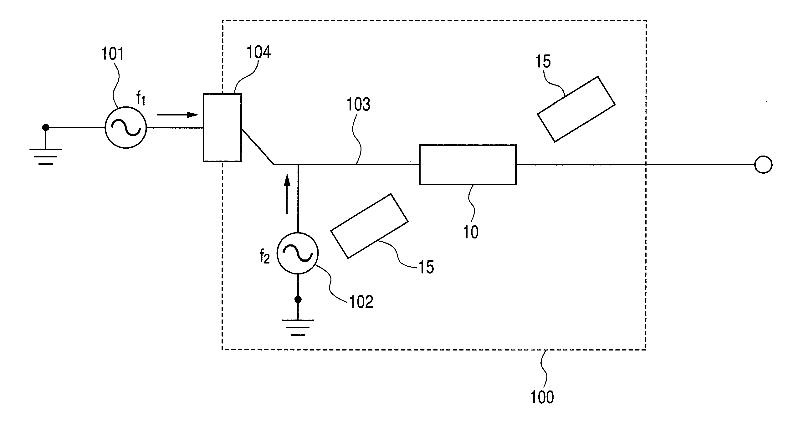
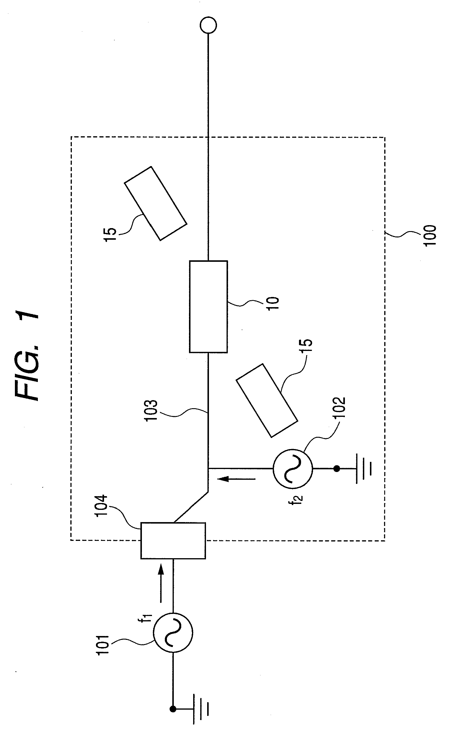
[0041]FIG. 1 shows an example of a frequency converter of the present invention. A frequency converter 100 includes: a frequency conversion device having a magneto-resistance element; a magnetic field application mechanism 15 applying a magnetic field to the frequency conversion device 10; a local oscillator 102 having a magneto-resistance element; an input terminal 104; and a wiring 103 electrically connecting the input terminal 104 and the local oscillator 102 to the frequency conversion device 10. The frequency converter 100 is an apparatus which outputs a difference signal between a high frequency signal f1 input from an input signal source 101 and a high frequency signal f2 applied by the l...


PUM


Abstract

The present invention provides a frequency converter including a frequency conversion device capable of accommodating a Si-series MMIC and also a GaAs-series MMIC by using a magneto-resistance element. A frequency converter according to an embodiment of the present invention includes: a frequency conversion device having a magneto-resistance element with a magnetization free layer, an intermediate layer, and a magnetization pinned layer; a magnetic field application mechanism for applying a magnetic field to the frequency conversion device; a local oscillator for applying a local oscillation signal to the frequency conversion device; and an input terminal electrically connected to the above frequency conversion device for receiving an external input signal. Further, the local oscillator includes a magneto-resistance element capable of generating the local oscillation signal by outputting an AC voltage according to a resistance change thereof.

Description

CROSS-REFERENCES TO RELATED APPLICATIONS[0001]This application is a continuation application of International Application No. PCT / JP2009 / 065304, filed on Sep. 2, 2009, the entire contents of which are incorporated by reference herein.BACKGROUND OF THE INVENTION[0002]1. Field of the Invention[0003]The present invention relates to frequency converter used in a radio communication apparatus or the like for performing frequency conversion.[0004]2. Related Background Art[0005]A non-linear element such as a semiconductor diode and FET has been used for a conventional frequency conversion device. The purpose of the frequency conversion is to input a signal having a certain frequency into a frequency conversion device and output a signal having a frequency component different from that of the input signal.[0006]The case of applying a current into a non-linear resistance r(i) will be discussed as a simplest example of performing the frequency conversion using the non-linear element. The curr...

Claims


Application Information

Patent Timeline
Patent Type & Authority Applications(United States)
IPC IPC(8): H02M5/00
CPCH01L43/08H03D7/00H03B15/006H10N50/10
Inventor MAEHARA, HIROKI
Owner CANON ANELVA CORP
Why Eureka
Try Eureka