

Suture securing device and method
- Summary
- Abstract
- Description
- Claims
- Application Information
AI Technical Summary
Benefits of technology
Problems solved by technology
Method used
Image

Examples
Embodiment Construction
[0050] The following is a list of unique terms used in the description of the invention:
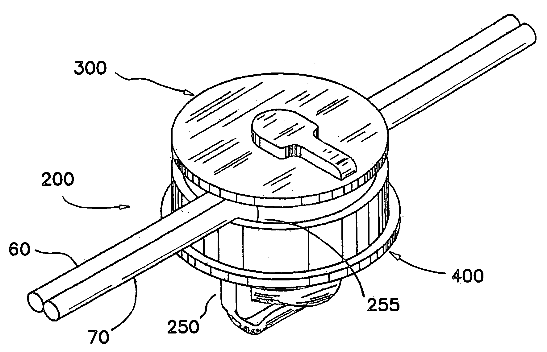
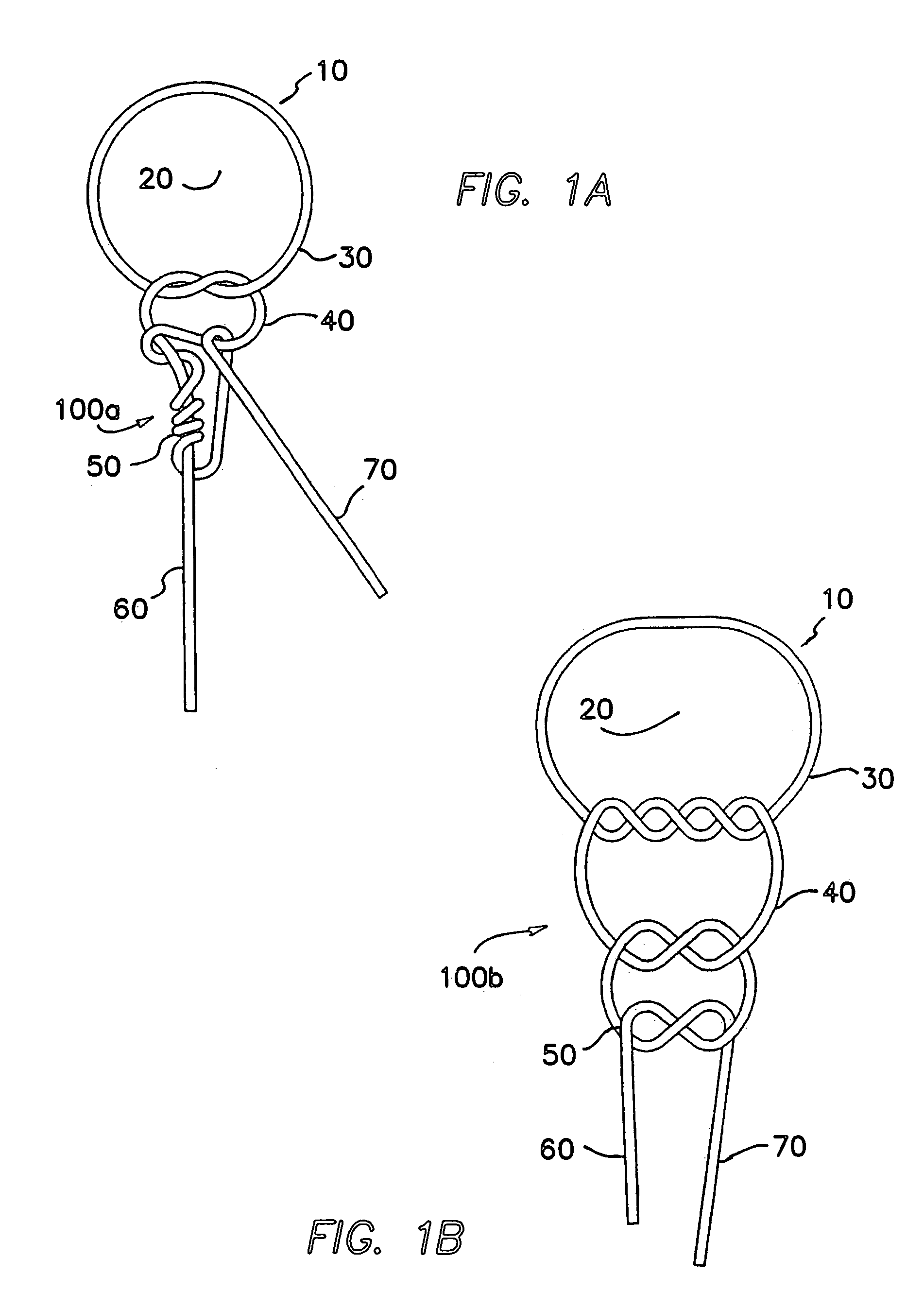
[0051] CLINCH—a device or component for securing a looped strand or strands of suture material in a manner resembling a tied knot in a tortuous pathway within and between tractive surfaces or faces.
[0052] TIED KNOT—a conventional surgical knot comprising multiple throws or combinations of simple tied knots.
[0053] THROW—a simple intertwining of strands forming a basic knot such as a “Granny Knot” or a “Square Knot”. Several basic or simple knots or throws are combined to form a complex knot.
[0054] PASSED SUTURE—a length of suture that has been passed through tissue in combination with an attached needle for the purpose of approximating, holding, repairing or securing tissue.
[0055] FREE ENDS—ends of a length of suture that extend before and after the suture has passed through a portion of the tissue.
[0056] TORTUOUS PATHWAY—a pathway through or between elements of a device that restricts motio...
PUM
 Abstract
Description
Claims
Application Information