Abrasion preventive structure of reciprocating compressor

a reciprocating compressor and preventive structure technology, applied in the direction of positive displacement liquid engines, piston pumps, liquid fuel engines, etc., can solve the problems of reducing assembly productivity and relatively large so as to reduce the number of construction parts, prevent contact parts, and simplify fabrication and assembly of construction parts

Inactive Publication Date: 2005-05-12
LG ELECTRONICS INC
View PDF5 Cites 64 Cited by
  • Summary
  • Abstract
  • Description
  • Claims
  • Application Information

AI Technical Summary

Benefits of technology

[0021] In addition, in order to achieve the above-mentioned objects, in a reciprocating compressor including a cylindrical container; a frame supported elastically inside the container; a reciprocating motor disposed in the frame and performing a linear reciprocating motion; a piston combined with a mover of the reciprocating motor and sucking / compressing fluid in the linear reciprocating motion; a cylinder receiving the piston movably and fixed to the frame so as to form a compression space; and plural resonance springs arranged between the mover or a spring supporting rod combined with the mover and the frame to make the mover of the reciprocating motor and the piston resonate together, an abrasion preventive structure of a reciprocating compressor in accordance with the present invention includes the frame constructed as a cylinder built-in type frame having a piston insertion hole; and a surface reinforcing layer made of material having lubricating ability and abrasion resistance and coated onto the inner circumference of the piston insertion groove of the cylinder built-in type frame.

Problems solved by technology

However, in the conventional reciprocating compressor, because the cylinder 60 is combined with the front frame 50, the combining portion between them has to be precisely processed, it is intricate to fabricate the frame 50 and the cylinder 60 precisely, and accordingly assembly productivity is lowered and relatively lots of construction parts are required.

Method used


Image

  • Abrasion preventive structure of reciprocating compressor
  • Abrasion preventive structure of reciprocating compressor
  • Abrasion preventive structure of reciprocating compressor

Examples


Embodiment Construction

[0029] Hereinafter, the preferred embodiment of the present invention will be described with reference to accompanying drawings.

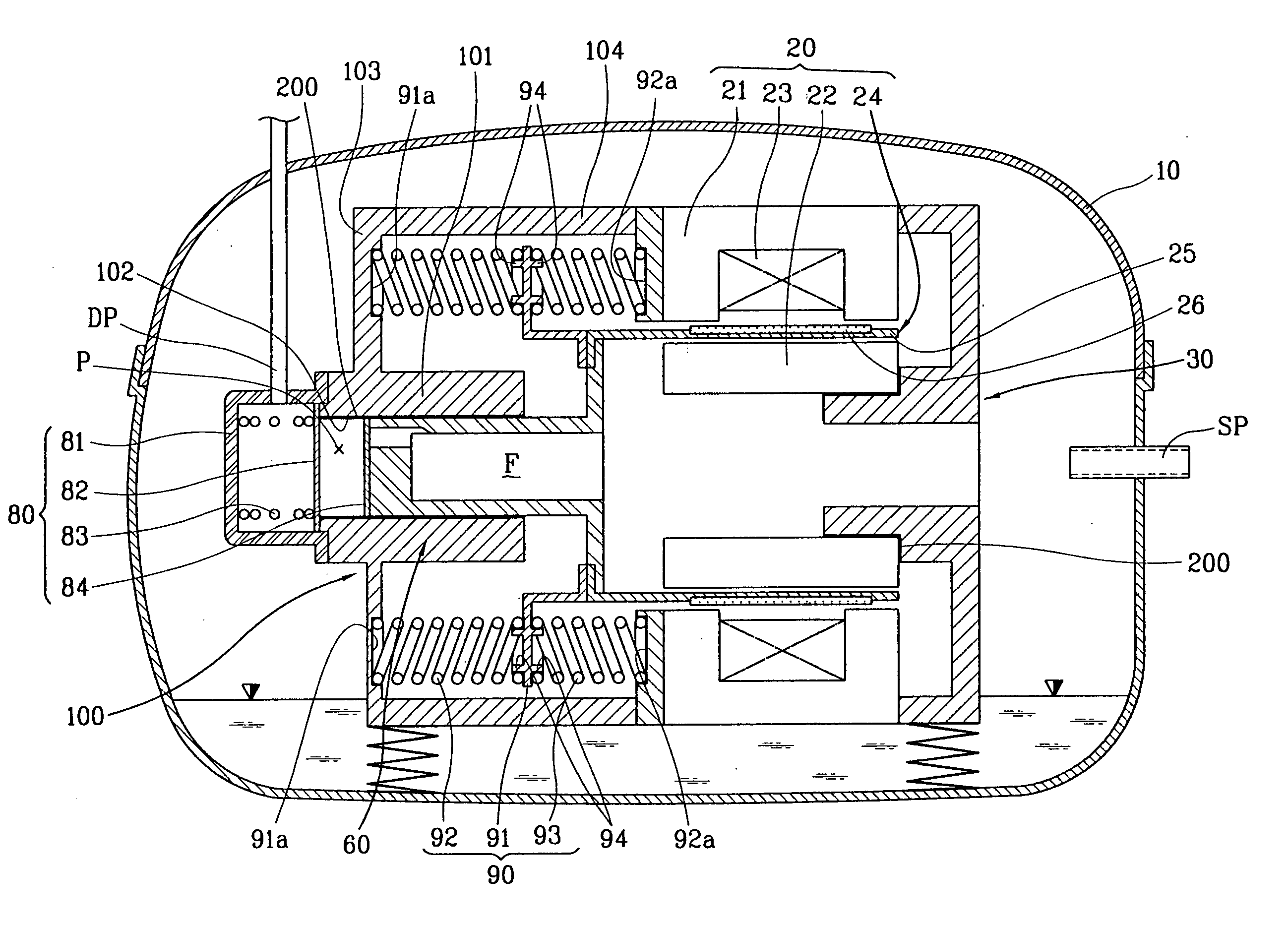
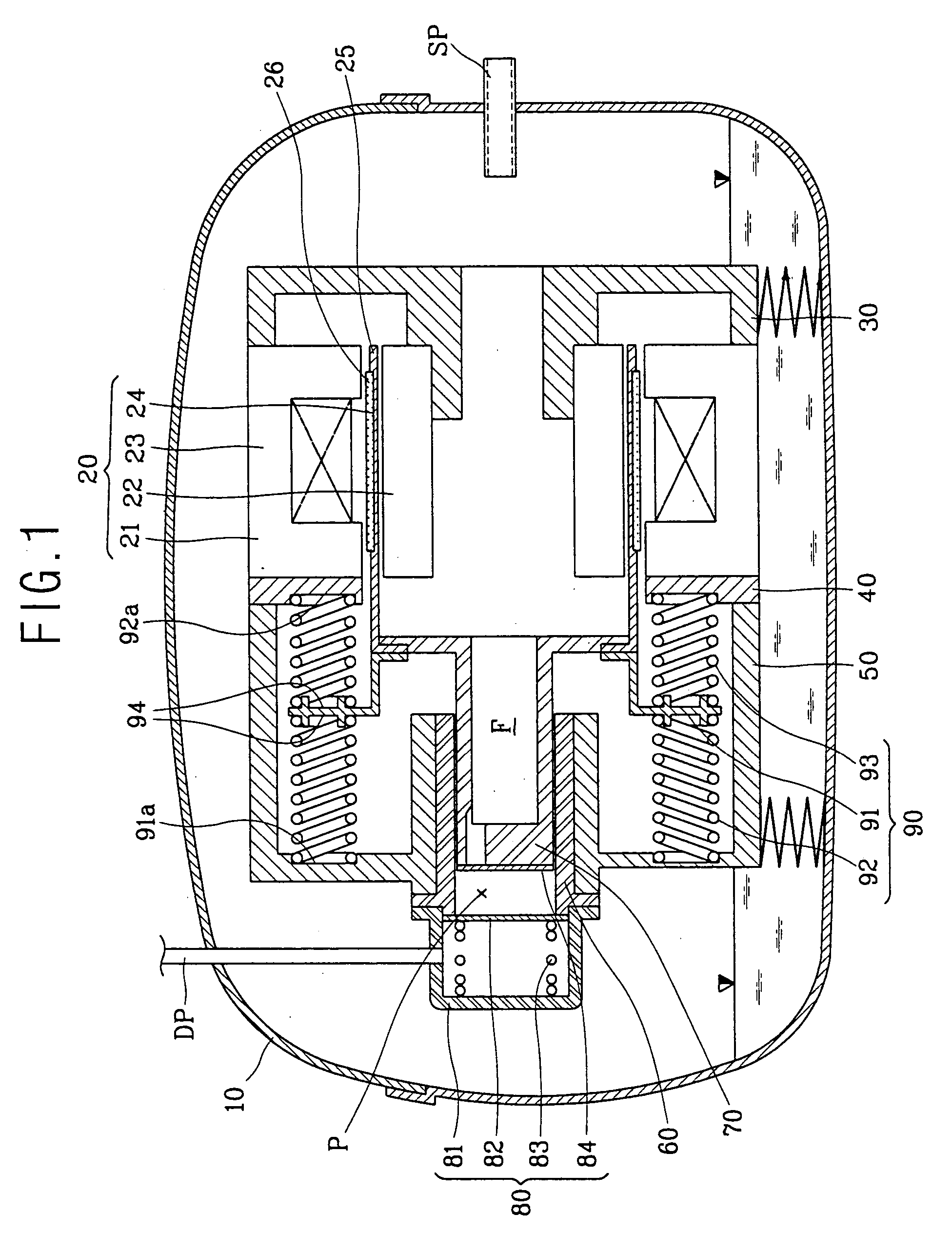
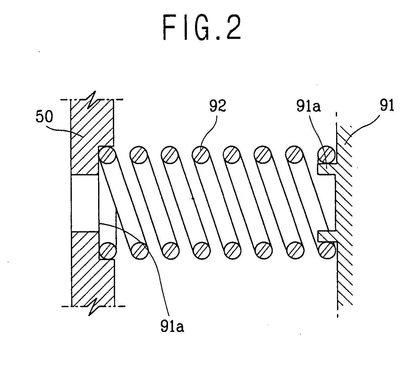
[0030]FIG. 3 is a sectional view illustrating a reciprocating compressor having an abrasion preventive structure in accordance with the present invention; FIG. 4 is a sectional view illustrating the abrasion preventive structure of the reciprocating compressor in accordance with the present invention; and FIG. 5 is a longitudinal sectional view illustrating a fixation portion of a resonance spring in the abrasion preventive structure of the reciprocating compressor in accordance with the present invention.

[0031] With reference to FIGS. 3˜5, in the reciprocating compressor, first a reciprocating motor 20 for generating linear reciprocating driving force is disposed in a container 10 having a certain shape, and a rear frame 30 and a middle frame 40 are respectively combined with the both sides of the reciprocating motor 20.

[0032] The reciprocating motor 20...


PUM

PropertyMeasurementUnit
structureaaaaaaaaaa
outer circumferenceaaaaaaaaaa
abrasion resistanceaaaaaaaaaa

Abstract

In an abrasion preventive structure of a reciprocating compressor, by forming a coating layer made of Ni—P alloy material having high hardness onto the surface of a frame at which front (92) and rear (93) resonance springs are contacted or spring mounting grooves (91a, 92a) of a spring supporting rod (91) or spring fixation protrusions or the inner circumference of a cylinder built-in type frame, although each resonance spring (92, 93) is rotated while repeating compression / relaxation, it is possible to prevent abrasion of the spring mounting grooves (91a, 92a) or the spring fixation protrusions, and accordingly reliability of the compressor can be improved.

Description

TECHNICAL FIELD [0001] The present invention relates to a reciprocating compressor, and in particular to an abrasion preventive structure of a reciprocating compressor which is capable of preventing abrasion at contact portions of construction parts, reducing the number of construction parts and simplifying fabrication process and assembly measure management of the construction parts. BACKGROUND ART [0002] In general, a reciprocating compressor sucks, compresses and discharges gas while a piston performs a liner reciprocating motion inside a cylinder. FIG. 1 is a longitudinal sectional view illustrating the conventional reciprocating compressor. [0003] As depicted in FIG. 1, the reciprocating compressor includes a cylindrical container 10; a reciprocating motor 20 disposed in the container 10 and generating a linear reciprocating driving force; a rear frame 30 and a middle frame 40 respectively supporting the both sides of the reciprocating motor 20; a front frame 50 combined with t...

Claims


Application Information

Patent Timeline
Patent Type & Authority Applications(United States)
IPC IPC(8): F04B35/04
CPCF04B35/045F05C2253/12F05C2201/0466
Inventor YOON, HYUNG-PYOLEE, KYEONG-WEON
Owner LG ELECTRONICS INC
Why Eureka
Try Eureka