Switch apparatus for use in vehicles

a technology for switches and vehicles, applied in mechanical devices, transportation and packaging, dashboard fitting arrangements, etc., can solve the problems of inability to visually check the position of switches, limited space on the periphery of steering wheels for arranging additional switches, and inability to touch operation by drivers, etc., to improve the operation reliability of switches, increase the space for arranging other switches, and low cost

Inactive Publication Date: 2005-05-12
KK TOKAI RIKA DENKI SEISAKUSHO
View PDF9 Cites 59 Cited by
  • Summary
  • Abstract
  • Description
  • Claims
  • Application Information

AI Technical Summary

Benefits of technology

[0006] The present invention provides a switch apparatus for vehicles, which improves the operation reliability of a switch included therein that the driver has to feel for to operate, and increases space for arranging other switches at a low cost.
[0008] Another aspect of the present invention is a switch apparatus for use in a vehicle by an operator. The switch apparatus includes a cover having a front surface facing the operator and a rear surface opposite to the front surface. A lever switch includes a lever that is arranged near the rear surface of the cover and operated by the operator. A viewer is arranged on the cover for enabling the operator to visually check operation of the lever.
[0009] A further aspect of the present invention is a switch apparatus for use in a vehicle by an operator. The switch apparatus includes a cover having a front surface facing the operator and a rear surface opposite to the front surface. A touch switch is arranged on or near the rear surface of the cover and operated by the operator. A viewer is arranged on the cover for enabling the operator to visually check operation of the touch switch.
[0010] Another aspect of the present invention is a switch apparatus for a use in a vehicle, including a column, by an operator. The switch apparatus includes a support supported on the column. A switch is arranged on the support and operated by the operator. A paddle is fixed to the support near the switch. A viewer is arranged on the paddle for enabling the operator to visually check operation of the switch.
[0012] Another aspect of the present invention is a switch apparatus for use in a vehicle, including a vehicle component having a recess, by an operator. The switch apparatus includes a cover attached to the recess and having a front surface facing the operator and a rear surface opposite to the front surface. A switch is arranged on the rear surface of the cover and operated by the operator. A viewer is arranged on the cover for enabling the operator to visually check operation of the switch.

Problems solved by technology

However, when the driver is not familiar with the characteristics of a switch apparatus that he or she operates, or when the driver operates a switch that he or she uses infrequently, the driver may not be confident of touch-operation.
Thus, the periphery of the steering wheel has limited space for arranging additional switches.
In such cases, the driver is able to easily operate the switches but is not able to visually check the position of the switches.
This does not improve the operation reliability of the switches, or ensure the operating of the switches.
Thus, locations for the switches are limited.
However, the disclosed apparatus uses a touch screen and a screen display, which results in relatively high costs.

Method used


Image

  • Switch apparatus for use in vehicles
  • Switch apparatus for use in vehicles
  • Switch apparatus for use in vehicles

Examples


first embodiment

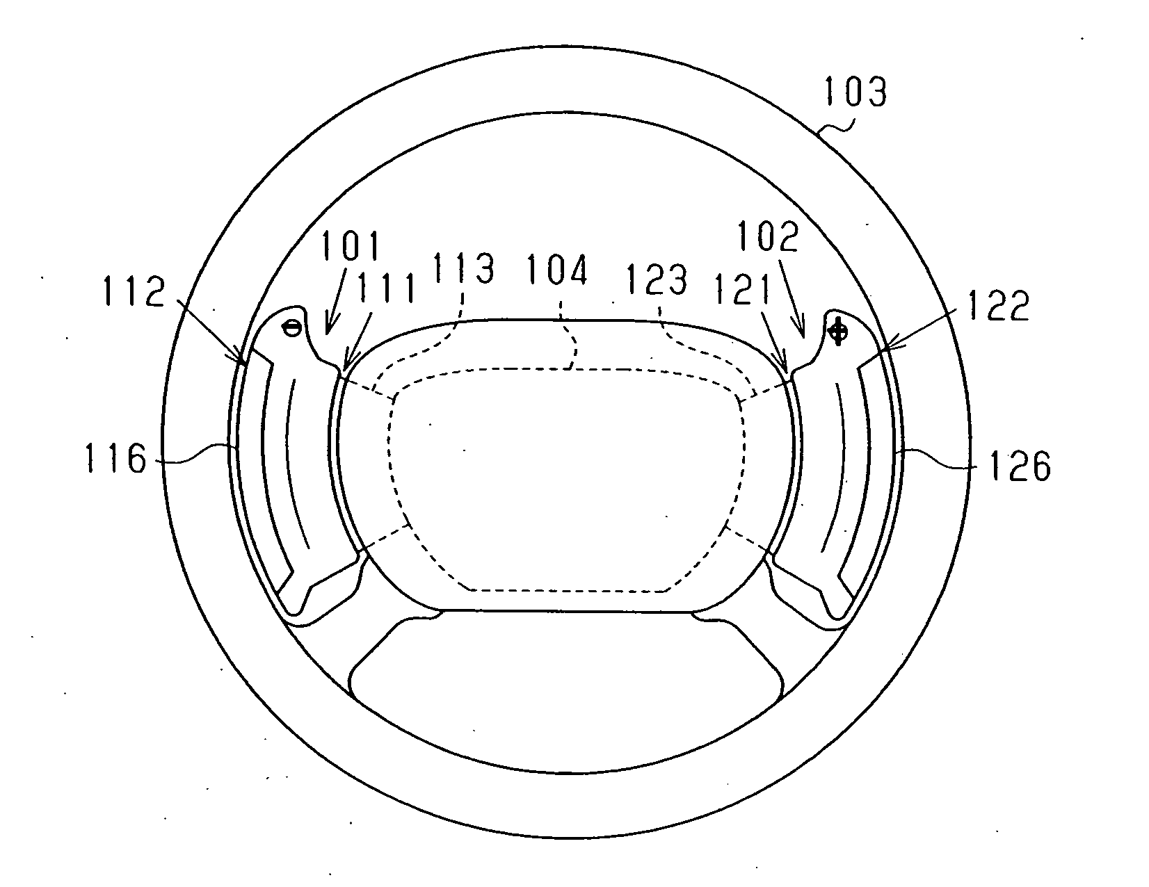
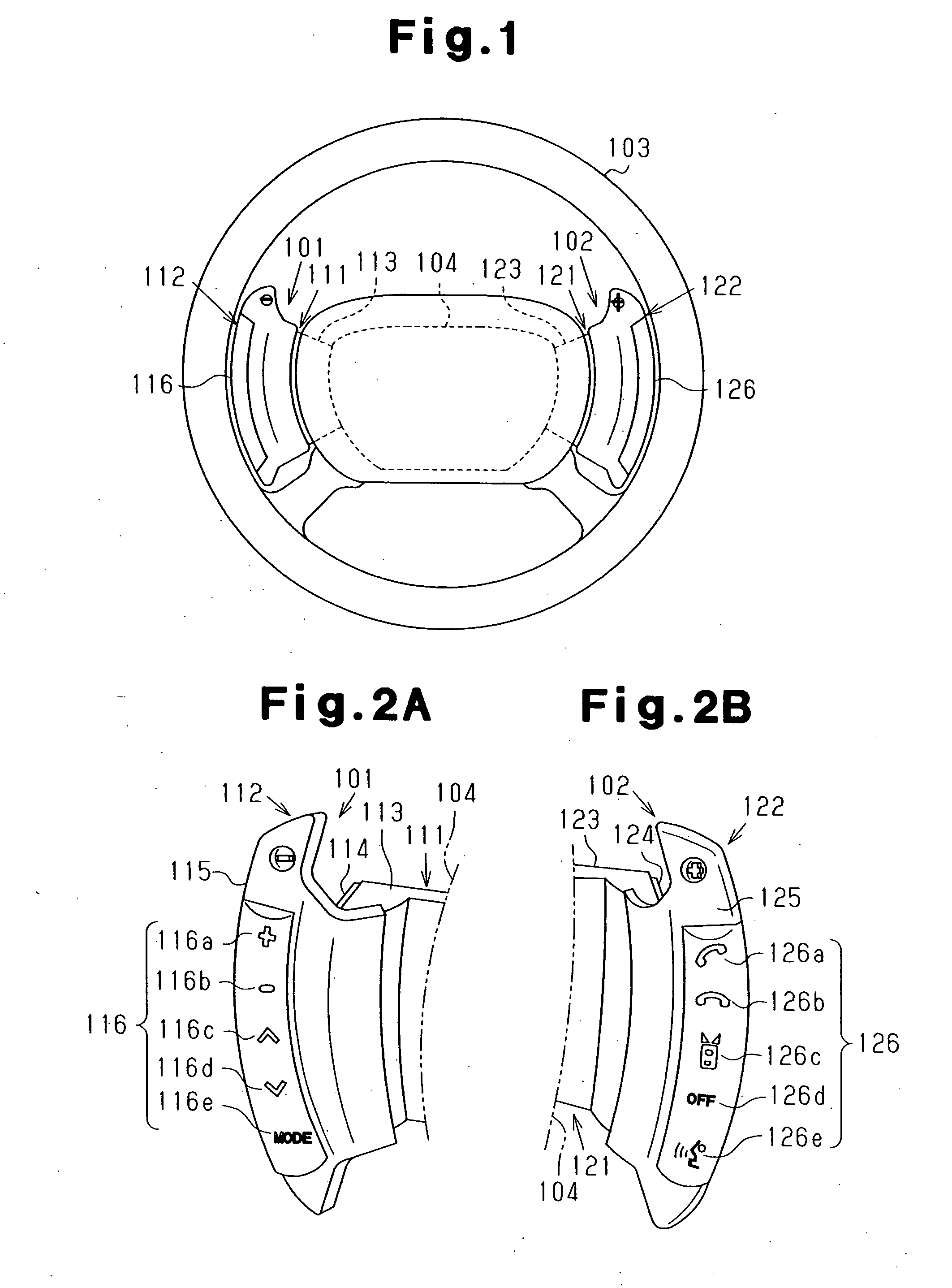
[0035] Vehicle switch apparatuses 101 and 102 according to a first embodiment of the present invention will now be described with reference to FIGS. 1 to 5. As shown in FIG. 1, the vehicle switch apparatus 101 is arranged on the left side of a column 104 of a steering wheel 103, and the vehicle switch apparatus 102 is arranged on the right side of the column 104. The vehicle switch apparatuses 101 and 102 are hereafter simply referred to as the switch apparatuses 101 and 102. Control levers for a turn signal switch, a front light switch, a wiper switch, etc. are arranged on the left and right sides of the column 104 but are not shown in the drawing.

[Switch Apparatus 101]

[0036] As shown in FIG. 1, the switch apparatus 101 includes a gearshift down switch 112 and a push switch 111. The gearshift down switch 112 has a window 116, which functions' as a viewer.

[0037] As shown in FIG. 2A, the gearshift down switch 112 includes a main body 113 (support), which is supported on the base o...

second embodiment

[0061] Vehicle switch apparatuses 105 and 106 according to a second embodiment of the present invention will now be described with reference to FIGS. 6 and 7.

[0062] As shown in FIG. 6, the vehicle switch apparatus 105 is arranged on the left side of a column 104 of a steering wheel 103, and the vehicle switch apparatus 106 is arranged on the right side of the column 104. The vehicle switch apparatuses 105 and 106 are hereafter simply referred to as the switch apparatuses 105 and 106. The switch apparatus 105 includes a gearshift down switch 151 and a lever switch 153. The lever switch 153 includes a lever 153a. The switch apparatus 106 includes a gearshift up switch 152 and a lever switch 156. The lever switch 156 includes a lever 156a.

[0063] As shown in FIG. 6, the gearshift down switch 151 includes a paddle 151a and a support 151b. The symbol “−” is marked on the top portion of the paddle 151a. The support 151b is formed integrally with the paddle 151a. The support 151b is suppo...

third embodiment

[0071] A door switch 107 according to a third embodiment of the present invention will now be described with reference to FIGS. 8A to 8C.

[0072] As shown in FIG. 8A, the door switch 107 is arranged at a position lower than an armrest 176 of a vehicle door 175 beside the driver's seat. In detail, the door switch 107 is arranged in an opening 175b of a recess 175a, which is formed in the vehicle door 175. The driver (operator) is able to open the vehicle door 175 by operating the door switch 107 from inside the vehicle.

[0073] As shown in FIG. 8B, the door switch 107 includes a cover 171 and a push switch 172. The cover 171 functions as a viewer. The push switch 172 is arranged at the rear side of the cover 171. The push switch 172 has an operation portion 172a, which projects toward the exterior of the vehicle.

[0074] The cover 171 is a transparent plate. In the middle portion of the opening 175b, an upper end portion and a lower end portion of the cover 171 are respectively fixed to...


PUM


Abstract

A vehicle switch apparatus for increasing space for other switches and ensuring operation of a switch when the switch must be felt for in order to be operated. The vehicle switch apparatus includes a paddle that has a front surface facing the driver and a rear surface opposite to the front surface. A push switch is arranged near the rear surface of the paddle and includes an operation portion operated by the driver. The paddle has a window for enabling the driver to visually check operation of the operation portion.

Description

BACKGROUND OF THE INVENTION [0001] The present invention relates to a switch apparatus for use in vehicles. [0002] To achieve high operation stability during driving of an automobile, it is preferable that the driver always looks in the travel direction of the automobile. In view of this, switch apparatuses for vehicles that are touch-operated have been proposed (refer, for example, to Japanese Laid-Open Patent Publication Nos. 2004-149086, 2003-143741, 2003-118416, 2002-166832, and 2002-50801). Such a switch apparatus enables the driver to feel for the desired switch. However, when the driver is not familiar with the characteristics of a switch apparatus that he or she operates, or when the driver operates a switch that he or she uses infrequently, the driver may not be confident of touch-operation. When operating a switch in such a case, the driver visually checks the position of the switch. Thus, it is preferable that switches are positioned relatively close to the driver's line ...

Claims


Application Information

Patent Timeline
Patent Type & Authority Applications(United States)
IPC IPC(8): B60K37/06B60Q1/14B60Q3/02F16H59/02H01H9/00
CPCB60K35/00B60K37/06B60K2350/1024B60K2350/1028F16H2059/0243B60Q1/1476B60Q1/1484B60Q3/0233F16H59/02B60K2350/928B60Q3/267B60K2370/143B60K2370/1438B60K2370/782
Inventor MIYAKO, MAMORUYAMAGUCHI, KAZUKIWASHINO, TAKAYUKIUMEMURA, SHINICHI
Owner KK TOKAI RIKA DENKI SEISAKUSHO
Why Eureka
Try Eureka