System and method for controlling the acoustic signature of a device

a technology of acoustic signature and a control system, which is applied in the direction of process and machine control, vehicle position/course/altitude control, instruments, etc., can solve the problems of aircraft pressure disturbance, disturbingly loud sound, and moving sound at the speed of sound

Inactive Publication Date: 2005-05-12
SUPERSONIC AEROSPACE INT
View PDF6 Cites 93 Cited by
  • Summary
  • Abstract
  • Description
  • Claims
  • Application Information

AI Technical Summary

Benefits of technology

[0009] In one embodiment, a system for controlling the acoustic signature of a device comprises a processor operable to receive information regarding the flight condition of the device during operation, and to determine the current acoustic level of the device based on the current operating condition information. The processor generates a signal indicating the acoustic level, and further generates information that can be used to control the operating condition of the device to achieve a desired acoustic level.

Problems solved by technology

When an object such as an airplane travels through air, the movement of the plane causes a pressure disturbance that moves at the speed of sound.
Since the front of a supersonic aircraft generates an increase in ambient pressure, and the rear generates a decrease in pressure, the variation in propagation speed causes aircraft pressure disturbances to stretch out as they propagate to the ground.
The abrupt compressions (also known as shocks) create a disturbingly loud sound.
Additionally, the shock waves may cause structural damage to surrounding buildings.
Rare minor damage may occur with 2 to 5 pounds overpressure.
Supersonic Transports (SSTs) are therefore restricted to supersonic flight across water, thereby limiting the usefulness of the planes.

Method used


Image

  • System and method for controlling the acoustic signature of a device
  • System and method for controlling the acoustic signature of a device
  • System and method for controlling the acoustic signature of a device

Examples


Embodiment Construction

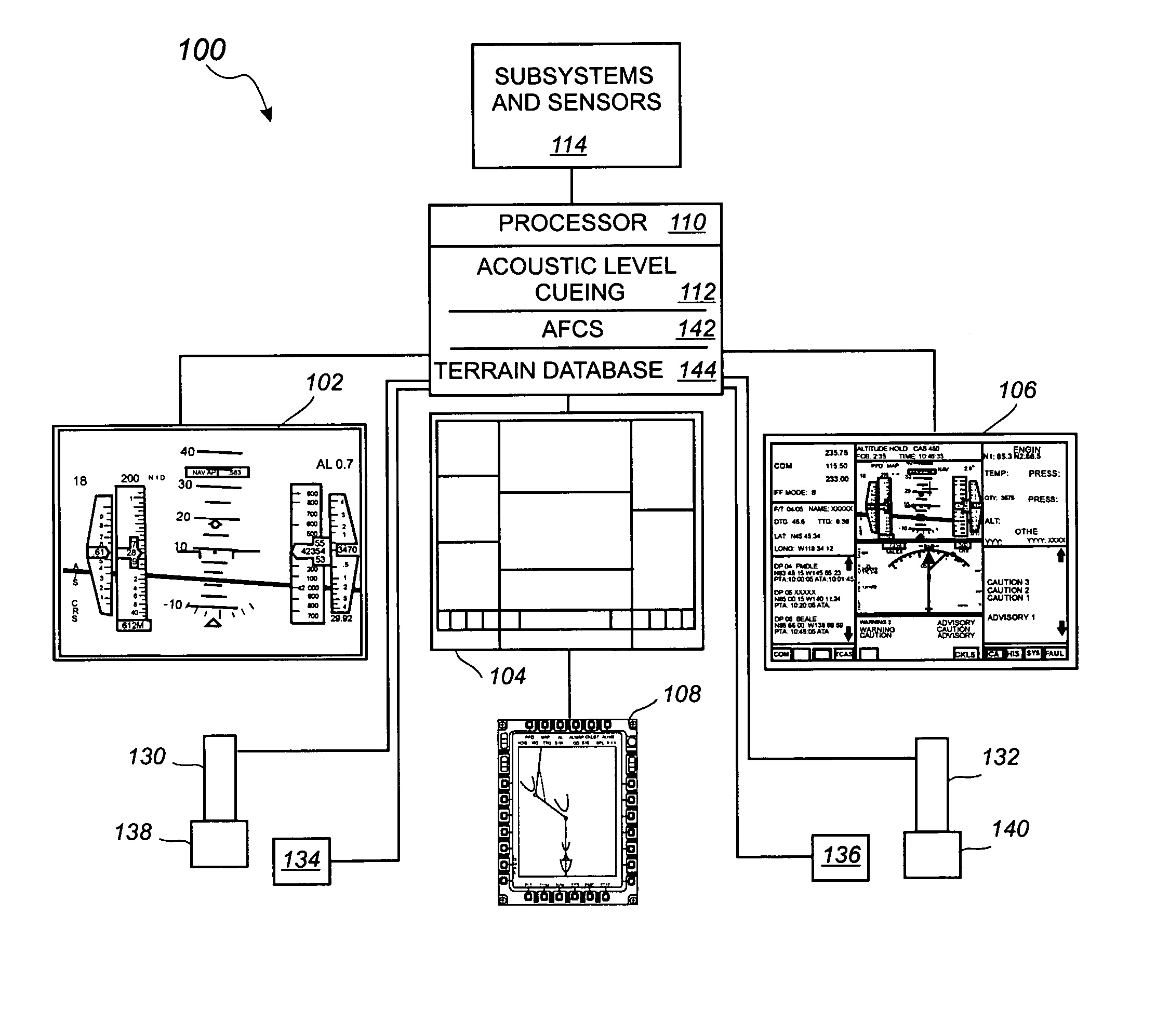
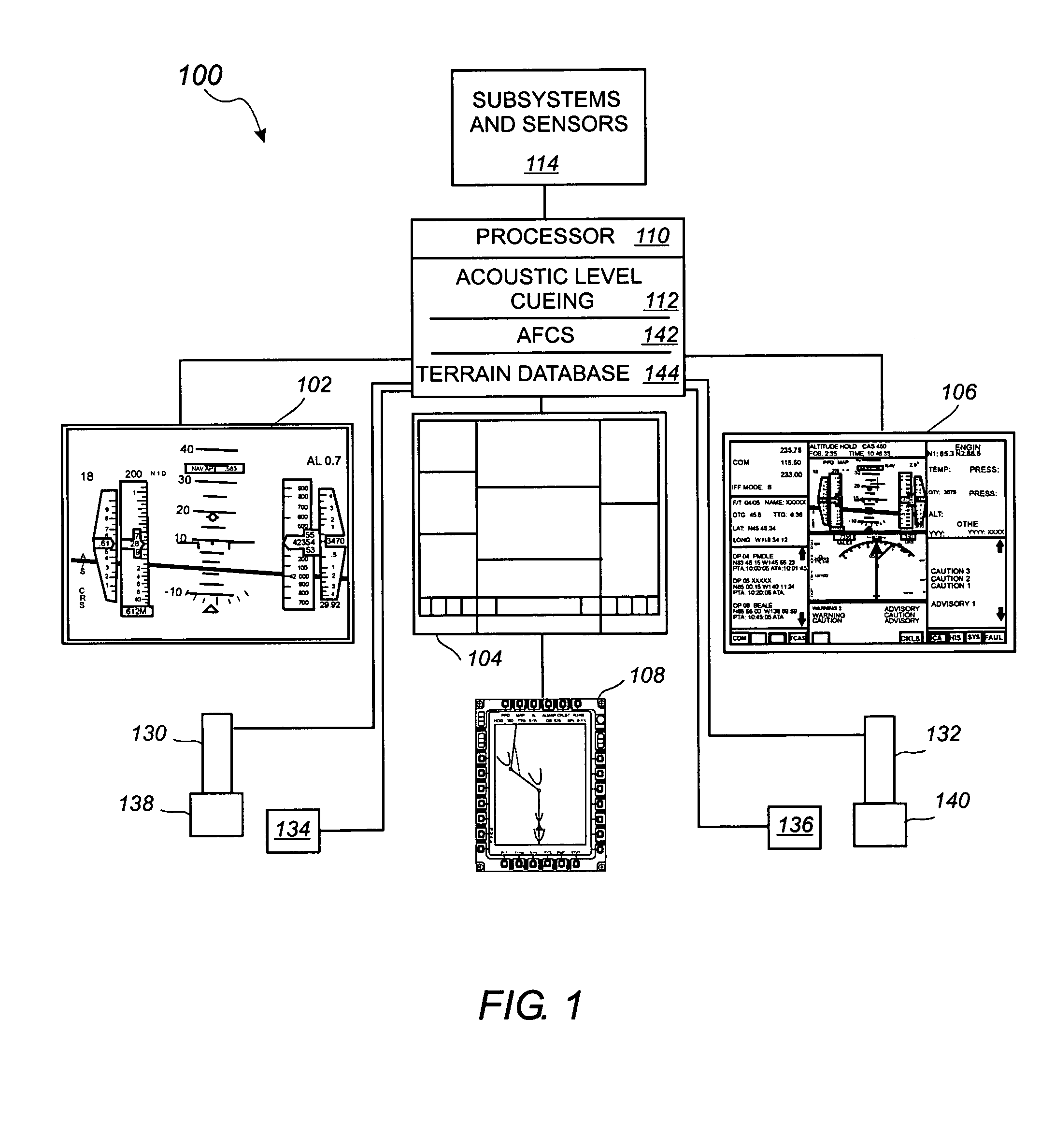
[0022] Referring to FIG. 1, a diagram of an embodiment of processing system 100 capable of generating aural, tactile, and visual cues regarding the strength of an aircraft's acoustic signature and shock wave as the aircraft approaches and enters supersonic regimes. Various cues can be presented via lights, buzzers, small high frequency movements on control grips, and one or more crewstation displays 102, 104, 106, 108.

[0023] Processor 110 executes APL cueing logic 112 to analyze the operational state, the surrounding environment, and the planned flight route, of the aircraft. Cues generated by APL cueing 112 can inform the pilot of current, past, and predicted acoustic levels, as well as action to take to reduce the strength of the acoustic signature to a pre-specified, or desired, level. One or more of the cues can be color-coded. For example, cues can be green to indicate that the strength of the shock wave is within a desired level; yellow to indicate that the strength of the sh...


PUM


Abstract

A system receives information regarding current flight conditions of a device such as an aircraft and determines the acoustic level of the sonic boom and/or other noise generated by the device during operation. The current acoustic level is compared to a desired level, and various cues are displayed to operators regarding corrective actions that can be taken to reduce or maintain the acoustic level at the desired level. The system also predicts future acoustic levels based on current operating conditions, and varies the urgency of the cues based on whether and how quickly the device will exceed the desired acoustic level. Options to limit maneuvers and to automatically adjust operating condition parameters can be enabled. Options to display additional information regarding past, current, and predicted acoustic levels can also be selected. Signals that can be used to automatically control the acoustic level of a device during operation can also be generated for use in devices that can operate autonomously.

Description

BACKGROUND OF THE INVENTION [0001] When an object such as an airplane travels through air, the movement of the plane causes a pressure disturbance that moves at the speed of sound. By way of example, the sound waves created by the nose of the plane will travel in an outward direction away from the aircraft. The air ahead of the plane receives the sound waves before the arrival of the aircraft, so that when the aircraft arrives, the air flows around the plane. As the airplane approaches the speed of sound, the sound waves merge closer and closer together at the front of the plane. When the aircraft is moving at the speed of sound the sound waves merge together into a “shock wave” which is an almost instantaneous line of change in pressure, temperature and density. [0002] An aircraft traveling at supersonic speed will generate a bow shock wave from the nose of the airplane and a tail shock wave created by the tail of the plane. The tail shock wave is created by an under pressurization...

Claims


Application Information

Patent Timeline
Patent Type & Authority Applications(United States)
IPC IPC(8): B64C30/00B64D45/00G01H17/00
CPCG01H17/00B64C30/00G08G5/0021G08G5/0039G08G5/0052G05D1/106
Inventor BERSON, BARRY L.BIALECKI, LARRY J.BUCK, PETER A.MORGENSTERN, JOHN M.
Owner SUPERSONIC AEROSPACE INT
Why Eureka
Try Eureka