Sealing Ring, Especially Radial Shaft Seal

a sealing ring and sealing technology, applied in the field of sealing rings, can solve problems such as untimely wear of these parts

Active Publication Date: 2005-05-12
KACO
View PDF11 Cites 66 Cited by
  • Summary
  • Abstract
  • Description
  • Claims
  • Application Information

AI Technical Summary

Benefits of technology

[0007] As a result of the configuration of the present invention, a second sealing element is pressure-loaded by a pressure acting on it as well as, optionally, by an overpressure of a medium penetrating from the medium side into the area between the seal elements. As a result of this additional pressing force, it is prevented that the second sealing element can lift accidentally off the movable machine part causing leakage when an overpressure occurs, for example, in the case of seal tightness testing or the like.
[0008] Furthermore, when operating pressureless, it is prevented that as a result of excessive friction between the second sealing element and the rotating machine part an untimely wear of these parts will occur. It is moreover advantageous th...

Problems solved by technology

Furthermore, when operating pressureless, it is prevented that as a result of excessive friction be...

Method used


Image

  • Sealing Ring, Especially Radial Shaft Seal
  • Sealing Ring, Especially Radial Shaft Seal
  • Sealing Ring, Especially Radial Shaft Seal

Examples


Embodiment Construction

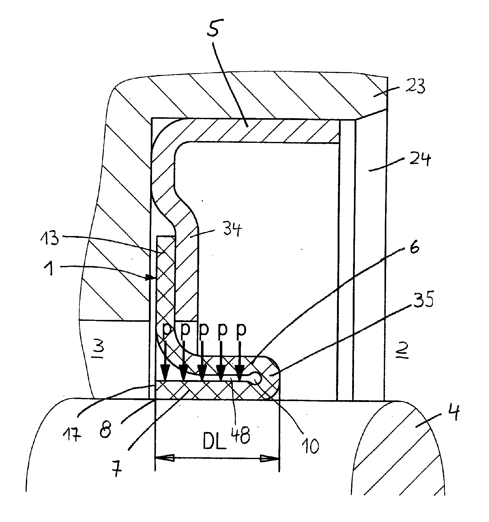
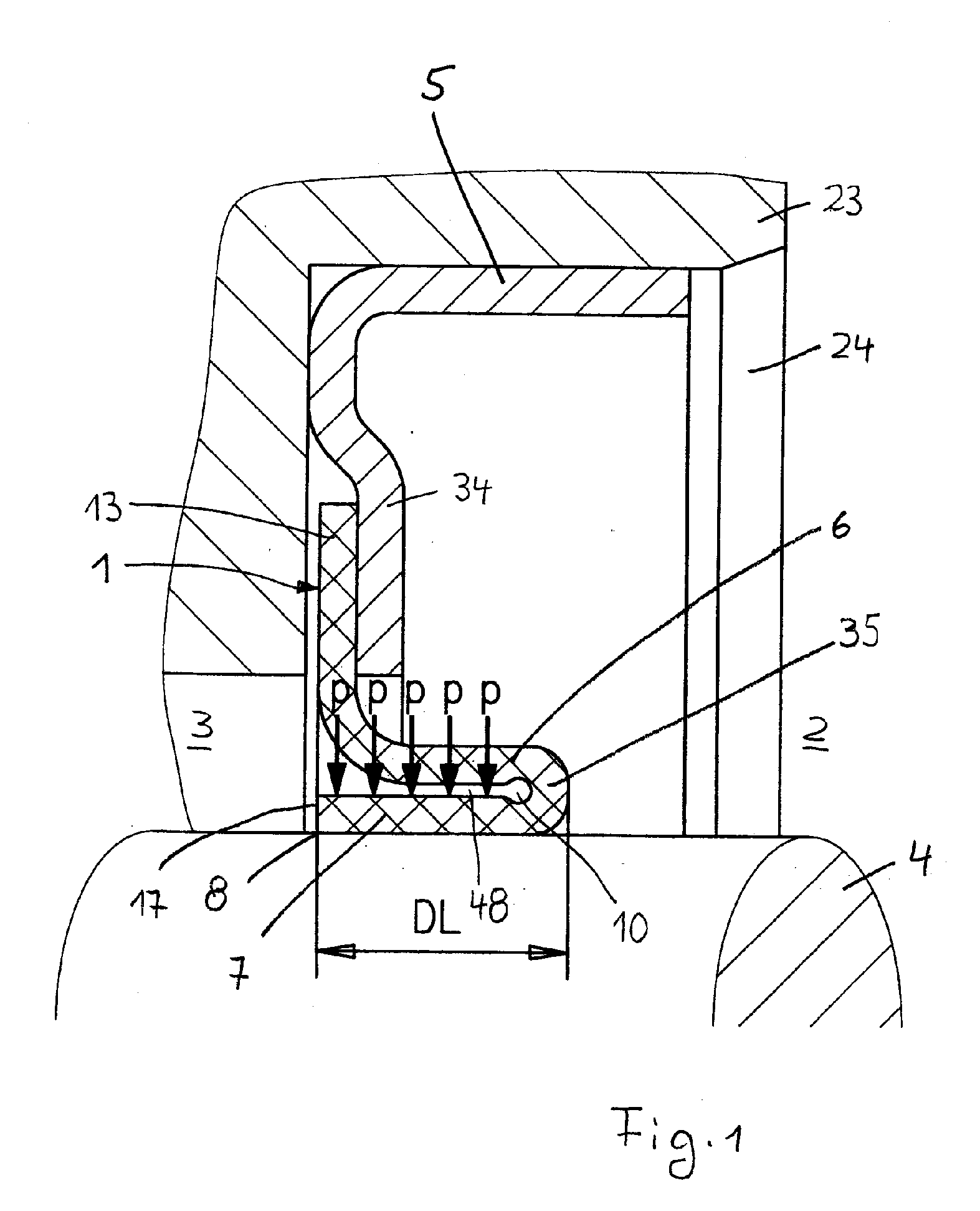
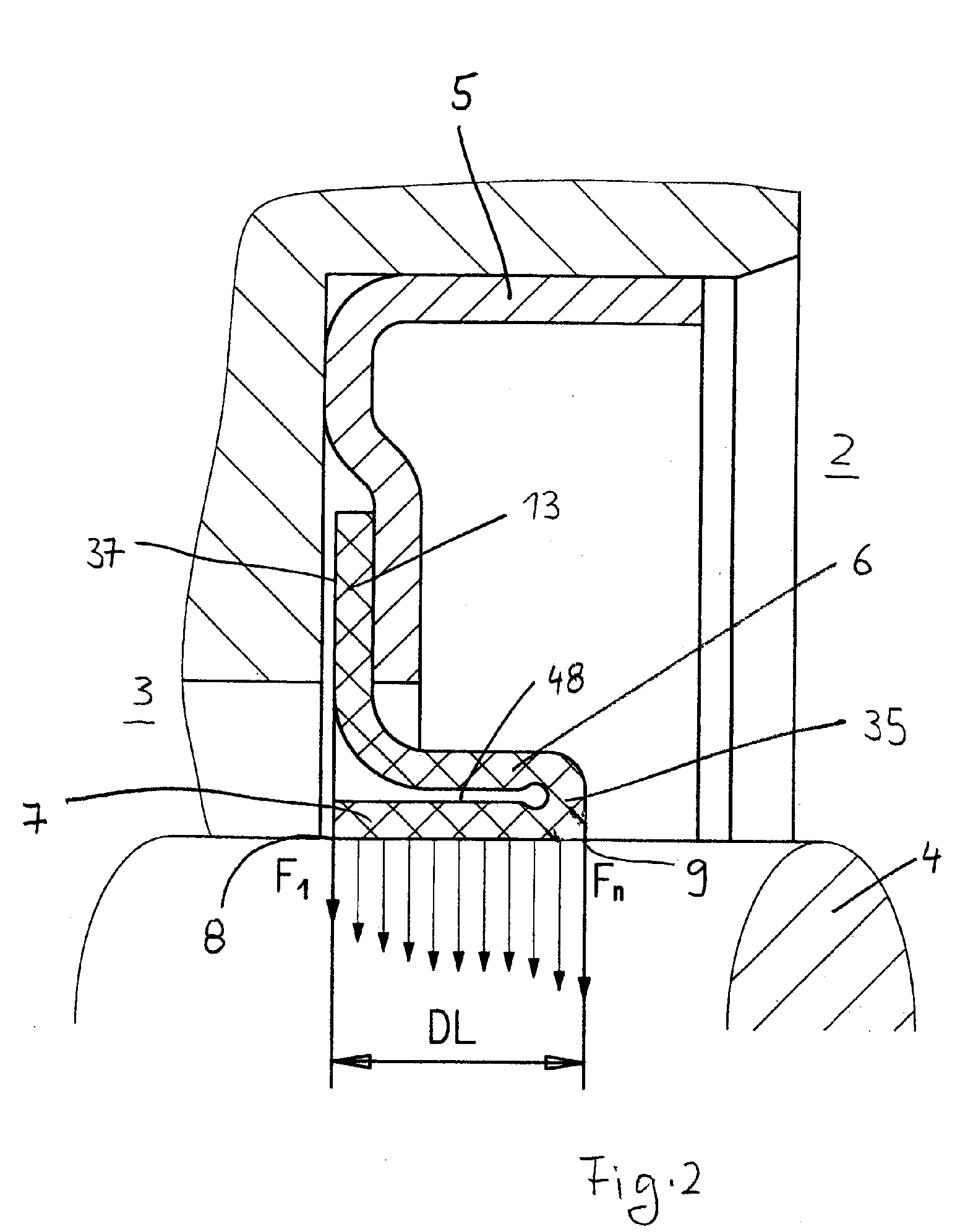
[0033] The sealing ring illustrated in FIG. 1 is a radial shaft seal for sealing a shaft 4. The shaft projects through a central opening of a housing 23 of a stationary machine part (not illustrated) such as an engine or drive module. In a receptacle 24 of the housing 23, the sealing ring provided with a cup-shaped seal housing 5 is inserted. The sealing disk 1 is arranged on the seal housing 5 and is comprised preferably of polytetrafluorocarbon, especially polytetrafluoroethylene. Of course, it can be made of any of other suitable material. The sealing disk 1 has a radial outer seal section that forms a fastening part 13 and connects the sealing disk 1 to the seal housing 5. The radial inner annular section of the sealing disk 1 is elastically deformed and thus forms a seal part 6, 7 with which the sealing disk 1 seals relative to the shaft 4. The fastening part 13 is formed by a radially extending outer section which in the mounted position of the sealing ring extends approximate...


PUM


Abstract

A sealing ring has a sealing disk having a fastening part and a seal part. The fastening part is connected to a first stationary machine part and the seal part seals a movable machine part and is oriented in an axial direction toward an atmosphere side or a medium side of the sealing ring. The seal part has a first sealing element and a second sealing element adjoining the first sealing element and oriented in a direction opposite to the first sealing element in a mounted position of the sealing ring. The second sealing part rests against the rotary machine part under a radial force.

Description

BACKGROUND OF THE INVENTION [0001] The invention relates to a sealing ring, especially a radial shaft seal, piston seal, or rod seal, comprising a sealing disk having at least one fasting part provided on a first, preferably stationary, machine part, and wherein the sealing disk further has a seal part that is correlated with a second, preferably movable, machine part, preferably a shaft. The seal part extends in a direction toward an atmosphere side or medium side of the seal. [0002] Radial shaft seals are known that have a dynamic seal part that is formed by an annular disk of polytetrafluoroethylene. In the mounted state of the sealing ring (seal), it is outwardly curved in the direction toward the air (atmosphere) side and rests with a sealing lip on the rotating machine part, usually a shaft. The size of this known sealing ring is relatively small. Moreover, because the sealing lip is oriented toward the air side of the sealing ring, a special protective lip or dust lip is not ...

Claims


Application Information

Patent Timeline
IPC IPC(8): F16J15/32
CPCF16J15/3228F16J15/328F16J15/3244
Inventor UHRNER, KLAUS-JURGEN
Owner KACO
Why Eureka
Try Eureka