Medical device for percutaneous paravalvular leak and related systems and methods

a technology of medical devices and valves, applied in the field of medical devices, can solve the problems of reducing the pumping efficiency of the heart, increasing the stress of the heart, and the valves of the heart to fail functionally, so as to prevent the migration of the medical device, prevent the leakage of the leakage, and permanently seal the leakage

Inactive Publication Date: 2009-04-30
COHEREX MEDICAL
View PDF12 Cites 23 Cited by
  • Summary
  • Abstract
  • Description
  • Claims
  • Application Information

AI Technical Summary

Benefits of technology

[0010]In accordance with yet another embodiment of the present invention, another medical device is provided. The medical device includes a frame member having at least two elongated arms biased in two different directions. A tissue in-growth member configured to be attached to the frame member to promote tissue growth and permanently seal the leak. In one embodiment, the two different direction in which the at least two elongated arms are biased are substantially opposite one another. In another embodiment, the at least two elongated arms include at least two pair of elongated arms. Tines may be associated with the elongated arms to engage walls surrounding the paravalvular leak and prevent migration of the medical device.

Problems solved by technology

A relatively common mode of heart-failure is for the valves of the heart to fail functionally.
This may happen due to age, disease or many other factors, but the result is a reduction in the pumping efficiency of the heart which increases the amount of stress that the heart experiences in order to move the same amount of blood.
In other words, the heart becomes less efficient and needs to work harder to maintain a healthy flow of blood.
In cases where the ring or (other attachment device or system) is not entirely incorporated into the heart around its entire periphery, leaks may occur between the natural heart tissue and the implant.
In these valve implants, leaks may be more common than those implanted surgically.

Method used


Image

  • Medical device for percutaneous paravalvular leak and related systems and methods
  • Medical device for percutaneous paravalvular leak and related systems and methods
  • Medical device for percutaneous paravalvular leak and related systems and methods

Examples


Embodiment Construction

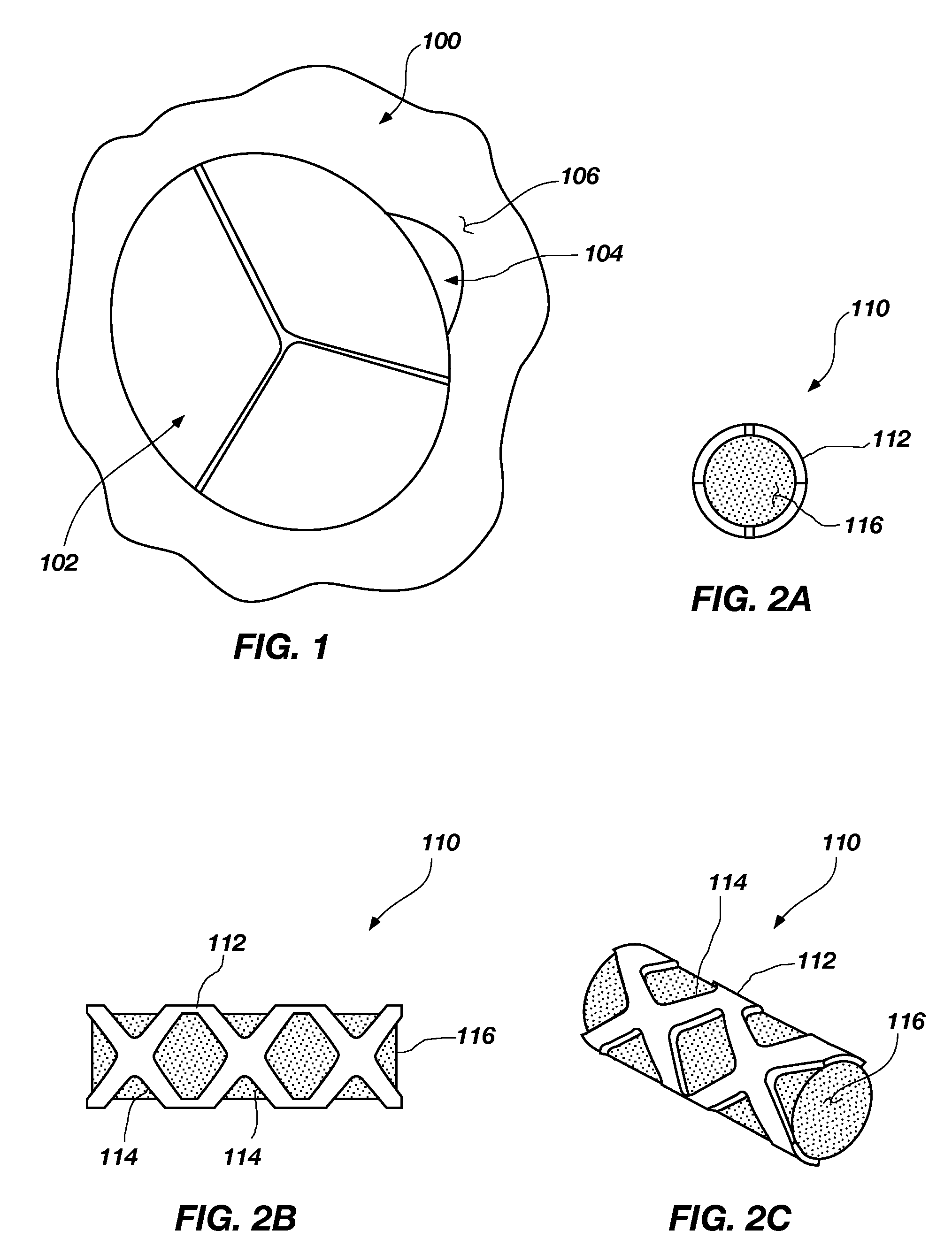
[0024]FIG. 1 illustrates an artificial valve 100 that may include, for example, a multi-leaflet structure 102 and that may be implemented in an appropriate manner as will be appreciated by those of ordinary skill in the art. Additionally, a small opening or space 104 between the heart 106 and the valve 100 is shown as may occur in some instances of valve replacement as has been described hereinabove. This opening or space 104 results in undesired leaking during pumping of the heart and is termed a valvular or paravalvular leak. Various embodiments of the present invention are described herein for blocking, plugging or otherwise occluding the space 104 and reducing or eliminating any leaks therethrough.

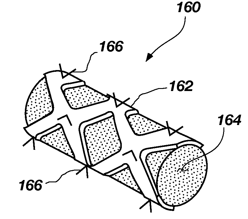
[0025]FIGS. 2A-2C illustrates an embodiment of a medical device 110 that is sized and configured to be positioned at a valvular leak (e.g., within space 104) and to block the unwanted flow of blood therethrough. The medical device 110 may include a tubular, multicellular frame member 1...


PUM


Abstract

The present invention provides devices, systems and methods for closing a paravalvular leak. In accordance with one embodiment, a medical device includes at least one multicellular frame member configured to be implanted at a paravalvular leak. The medical device further includes at least one tissue in-growth member associated with the frame member, the tissue in-growth member being configured to promote tissue growth and permanently maintain the frame member at the leak. The frame member may be self expanding device formed, for example, of a shape-memory alloy. The tissue in-growth member may be formed from a polymer material. In one particular embodiment, the frame member may be a substantially tubular structure and the tissue in-growth member may be disposed within an interior space defined by the tubular structure. In another embodiment, the frame ember may be a substantially flat or planar structure.

Description

CROSS-REFERENCE TO RELATED APPLICATION[0001]This application claims the benefit of Unites States Provisional Patent Application Ser. No. 60 / 981,454, filed Oct. 19, 2007, entitled FOR PERCUTANEOUS PARAVALVULAR LEAK, the disclosure of which is incorporated by reference herein in its entirety.TECHNICAL FIELD[0002]The present invention relates generally to medical devices and, more particularly, to medical devices that may be delivered percutaneously for repair of paravalvular leaks.BACKGROUND[0003]A relatively common mode of heart-failure is for the valves of the heart to fail functionally. This may happen due to age, disease or many other factors, but the result is a reduction in the pumping efficiency of the heart which increases the amount of stress that the heart experiences in order to move the same amount of blood. In other words, the heart becomes less efficient and needs to work harder to maintain a healthy flow of blood.[0004]When one's heart valves begin to fail, they may, fo...

Claims


Application Information

Patent Timeline
Patent Type & Authority Applications(United States)
IPC IPC(8): A61F2/24
CPCA61F2/24A61F2250/0069A61F2/2445A61F2/2409A61F2/246
Inventor MILES, SCOTT D.DAVIS, CLARK C.LINDER, RICHARD J.
Owner COHEREX MEDICAL
Why Eureka
Try Eureka