
Mounting system for rotary damper

a technology of mounting system and rotary damper, which is applied in the direction of steering device, cycle equipment, transportation and packaging, etc., can solve the problems of unstable steering system in motorcycles, rapid increasing rotational oscillation, and certain amount of undamped motion

Inactive Publication Date: 2009-12-15
VANVALKENBURGH CHARLIE N
View PDF10 Cites 2 Cited by
  • Summary
  • Abstract
  • Description
  • Claims
  • Application Information

AI Technical Summary

Benefits of technology

[0013]Accordingly, one object of the present invention is to provide a mounting system for a rotary damper on a motorcycle that eliminates undamped motion associated with existing prior art mounting systems.
[0014]Another object is to provide a mounting system that eliminates the free play in existing systems and allows for tight tolerances in the mounting system, but that does not bind or interfere with smooth steering action.
[0015]Still another object of the present invention is to provide a mounting system that can be easily removed so that maintenance can be performed on other motorcycle steering elements.
[0018]In operation, the mounting system of the present invention eliminates virtually all free play that is found in conventional prior art systems, while at the same time providing six degrees of movement so that the rotary damper is never placed in a bound condition. This prevents the rotary damper from being exposed to unnecessary forces that can damage the damper and cause seals in the damper to leak.
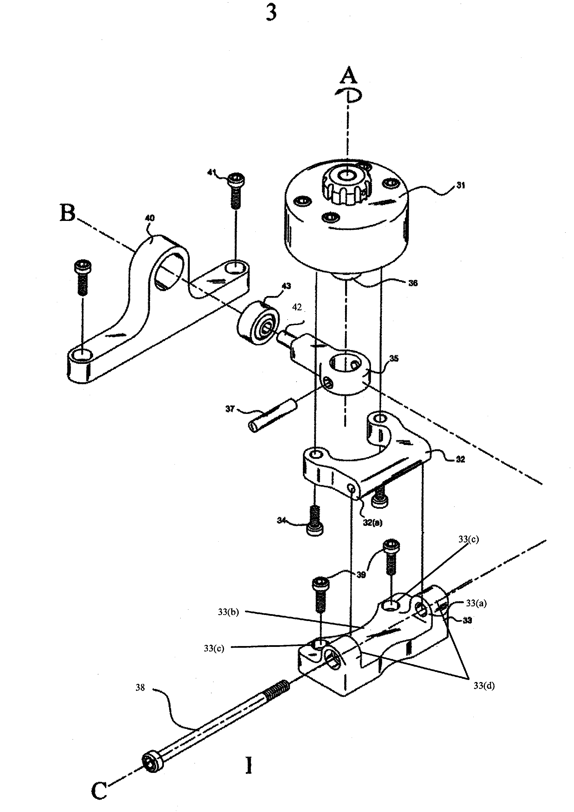
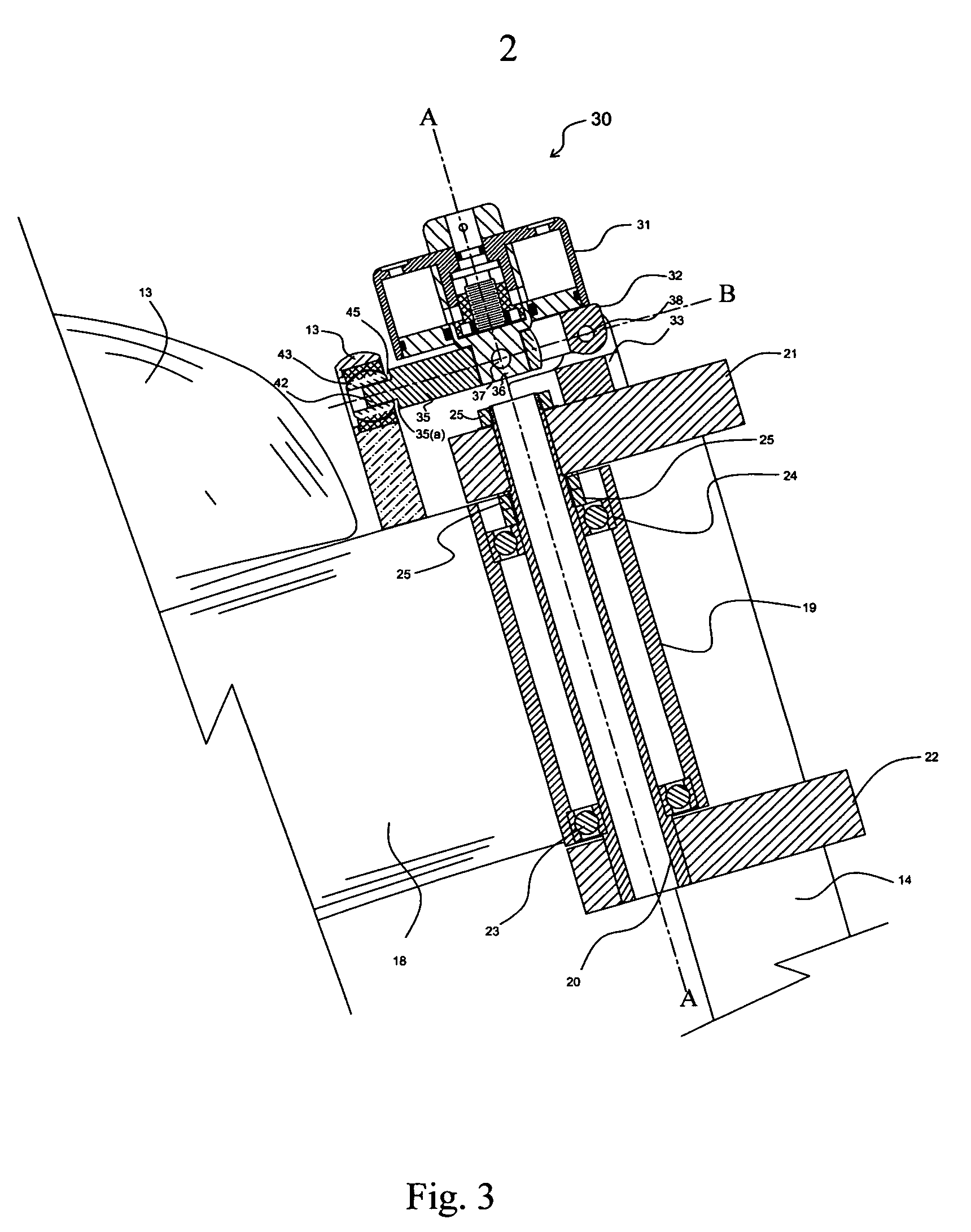
[0020]The mounting system of the present invention allows a rotary damper to be connected to the top triple clamp of a motorcycle steering system coaxially with the steering shaft and rotated about an axis that is traverse to the longitudinal axis of the motorcycle. This provides one axis of freedom which is necessary for unbound movement of the rotary damper. In addition, this feature of the invention allows the rotary damper to be rotated about this axis to provide quick and easy access to the top of the steering stem for maintenance or removal.
[0021]The arrangement of the damped member and the spherical bearing allows axial, as well as rotational movement, at this interface. This provides two additional axes of movement which are necessary for completely free movement of the rotary damper relative to the motorcycle frame. The frame bracket, which includes the spherical bearing, can be easily removed to facilitate removal of the rotary damper and maintenance on the steering system of the motorcycle.

Problems solved by technology

Under certain conditions, the steering system in a motorcycle can become unstable and develop rapidly increasing rotational oscillations in the steering head of the steering system.
However, if the steering system is disturbed by bumps, reduced loads during acceleration, or the front wheel contacting the ground after it has been raised in the air during very quick acceleration, head shake may occur.
These clearances cause a certain amount of undamped motion to occur during operation of a motorcycle, which is undesirable.
While the clearances can be reduced in order to reduce this undamped motion, this causes the mounting system to bind and interfere with smooth steering action—another equally undesirable result.
Another disadvantage of existing prior art mounting systems is that these systems are mounted over other motorcycle steering elements and must be completely removed before maintenance can be performed on these elements.

Method used


Image

  • Mounting system for rotary damper
  • Mounting system for rotary damper
  • Mounting system for rotary damper

Examples


Embodiment Construction

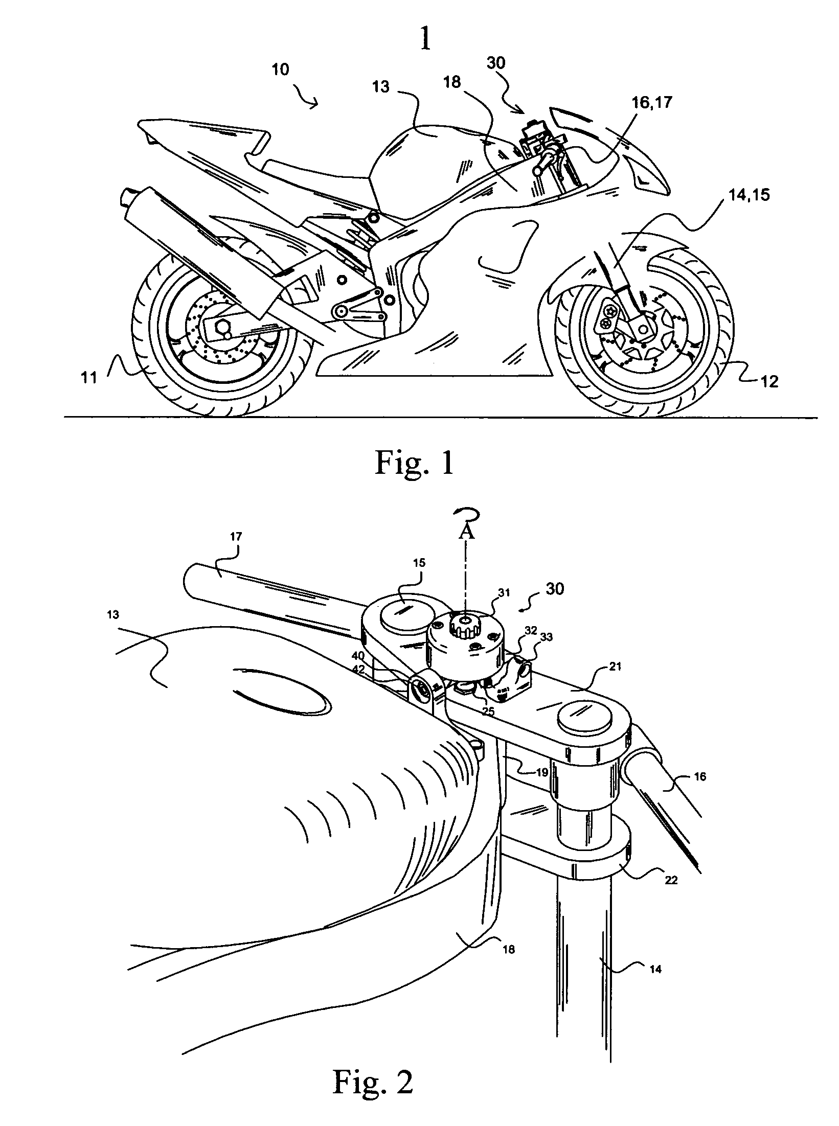
[0027]Referring to the drawings, FIG. 1 shows a conventional motorcycle 10 that includes one embodiment of the mounting system 30 of the present invention. Although the mounting system of the present invention is discussed in connection with a motorcycle, the invention is not limited to this type of application and can be used with any system that requires rotational damping. Motorcycle 10 includes a real wheel 11, a front wheel 12, a gas tank 13, and a rigid frame 18. Parallel forks, 14 and 15, support the motorcycle and provide suspension for front wheel 12.

[0028]As shown in FIG. 2, steering is controlled by inputs from a rider to the left and right handlebars, 16 and 17, which are mounted on the top of parallel forks 14 and 15. Forks 14 and 15 are rigidly mounted in an upper triple clamp 21 and a lower triple clamp 22, both of which are rotatably connected to rigid frame 18 through steering head 19.

[0029]Referring to FIG. 3, the steering mechanism for motorcycle 10 includes a ste...


PUM


Abstract

A mounting system for a rotary damper includes a base mount, a damper mount member, a damper arm, and a frame bracket including a spherical bearing. The base mount and frame bracket are designed to be mounted on a motorcycle and the damper mount member is rotatably connected to the base mount. The damper mount member and the damper arm are designed to be connected to the rotary damper. The damper arm is connected to the frame bracket using the spherical bearing and can move axially and rotationally with respect to the bearing. The mounting system allows the damper to move with respect to the motorcycle and prevents unnecessary forces from damaging the damper. The shapes and sizes of the various parts of the mounting system may vary depending on the type of motorcycle being used with the mounting system.

Description

[0001]A portion of the disclosure of this patent document contains material that is subject to copyright protection. The copyright owner has no objection to the facsimile reproduction by anyone of the patent document or the patent disclosure, as it appears in the U.S. Patent and Trademark Office patent file or records, but otherwise reserves all copyright rights whatsoever.CROSS-REFERENCES TO RELATED APPLICATIONS[0002]Not ApplicableSTATEMENT REGARDING FEDERALLY SPONSORED RESEARCH OR DEVELOPMENT[0003]Not ApplicableREFERENCE TO SEQUENCE LISTING OR COMPUTER PROGRAM LISTING APPENDIX[0004]Not ApplicableBACKGROUND OF THE INVENTION[0005]The present invention relates generally to mounting systems for rotary dampers used on motorcycles.[0006]More particularly, this invention pertains to mounting system for a rotary damper that reduces the amount of undamped motion associated with typical prior art mounting systems, while at the same time preventing any binding or interference with smooth ste...

Claims


Application Information

Patent Timeline
IPC IPC(8): B62K21/00
CPCB62K21/08
Inventor VANVALKENBURGH, CHARLIE N.
Owner VANVALKENBURGH CHARLIE N
Learn More