RFID tags adjusting to different regulatory environments, and RFID readers to so adjust them and methods

a technology of rfid tags and regulatory environments, applied in the field of wireless communications, can solve the problems of introducing noise and interference, a noisy radio-frequency environment, and a great deal of interference between competing signals, and achieving the effect of reducing noise and interferen

Active Publication Date: 2005-05-12
IMPINJ
View PDF29 Cites 132 Cited by
  • Summary
  • Abstract
  • Description
  • Claims
  • Application Information

AI Technical Summary

Problems solved by technology

Certain environments have proved to be more challenging for the successful deployment of an RFID system.
For example, in certain environments, a number of RFID readers and RFID tags may be utilized within a close proximity, resulting in a “noisy” radio-frequency environment in which a great deal of interference between competing signals may exist.
Furthermore, RF noise and interference may be introduced into a particular operating environment by other devices (e.g., cellular or mobile telephones, microwave devices, etc.).
Furthermore, reader synchronization is disallowed.

Method used


Image

  • RFID tags adjusting to different regulatory environments, and RFID readers to so adjust them and methods
  • RFID tags adjusting to different regulatory environments, and RFID readers to so adjust them and methods
  • RFID tags adjusting to different regulatory environments, and RFID readers to so adjust them and methods

Examples


Embodiment Construction

[0043] A method and an apparatus to configure an RFID system to be adaptable to a plurality of regulatory environments are described. In the following description, for purposes of explanation, numerous specific details are set forth in order to provide a thorough understanding of the present invention. It will be evident, however, to one skilled in the art that the present invention may be practiced without these specific details.

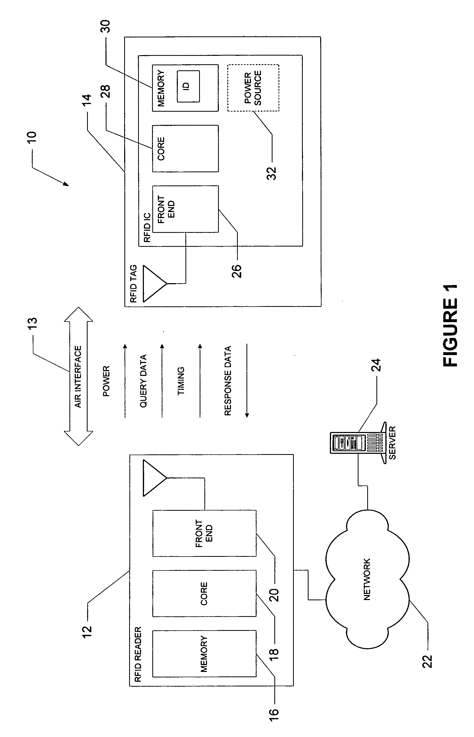
[0044]FIG. 1 is a diagrammatic representation of an exemplary RFID system 10, within which an embodiment of the present invention may be implemented. The RFID system 10 includes an RFID reader 12 that transmits information, via a wireless air interface 13, to one or more RFID tags 14. The air interface 13 enables the RFID reader 12, as shown, to provide power, query data and timing information to an RFID tag 14, responsive to which the RFID tag 14 may provide response data. Specifically, the RFID tag 14 may to scavenge power from a received radio-frequency...


PUM


Abstract

An RFID tag has an antenna to receive a configuration signal, and a circuit with a controller that can configure the RFID circuit responsive to the configuration signal. Configuring is such that the tag backscatters by impressing data either on the carrier frequency, or on a subcarrier in addition to the carrier signal, depending on the configuration signal. In the event of a subcarrier, the tag controller may optionally further determine a frequency of the subcarrier from the configuration signal. The tag may then be configured to backscatter differently, upon receiving a different configuration signal. A complementary reader transmits the configuration signal, thus imparting an operating parameter. The reader has an interface to receive an input indicative of a present geography, and a lookup table for determining an operating parameter based on the present geography. In one embodiment, the operating parameter is determined from regulations at that geographic location.

Description

RELATED APPLICATIONS [0001] This application is a continuation-in-part of U.S. application Ser. No. 10 / 824,049 and claims the priority benefits of U.S. Provisional Application No. 60 / 519,031, filed Nov. 10, 2003, and U.S. application Ser. No. 10 / 824,049 filed Apr. 13, 2004, each of which is incorporated herein by reference.FIELD OF THE INVENTION [0002] An embodiment relates generally to the field of wireless communications and, more specifically, to wireless communications in a radio-frequency identification (RFID) system. BACKGROUND OF THE INVENTION [0003] Radio-frequency identification (RFID) systems are being increasingly deployed to track items for a wide variety of purposes and in a wide variety of environments. For example, RFID systems are increasingly being deployed within supply chains to track inventory from manufacturing through retail distribution, for example. RFID systems are also being utilized to identify and track airline baggage within airports, to identify motor v...

Claims


Application Information

Patent Timeline
Patent Type & Authority Applications(United States)
IPC IPC(8): G06F7/00G06K7/00G06K19/07H01LH04Q5/22
CPCG06K19/0723G06K7/0008
Inventor DIORIO, CHRISTOPHER J.SUNDSTROM, KURT E.
Owner IMPINJ
Why Eureka
Try Eureka