Antenna system for a communication device

Active Publication Date: 2005-05-12
GOOGLE TECH HLDG LLC
View PDF8 Cites 123 Cited by
  • Summary
  • Abstract
  • Description
  • Claims
  • Application Information

AI Technical Summary

Problems solved by technology

The reduction in size provides additional challenges to the device designers to achieve adequate antenna electrical performance.
Testing has shown, for example, a degradation of performance of small clamshell phones at frequencies further away from half (½) wavel

Method used


Image

  • Antenna system for a communication device
  • Antenna system for a communication device
  • Antenna system for a communication device

Examples


Embodiment Construction

)

[0016] As required, detailed embodiments of the present invention are disclosed herein; however, it is to be understood that the disclosed embodiments are merely exemplary of the invention, which can be embodied in various forms. Therefore, specific structural and functional details disclosed herein are not to be interpreted as limiting, but merely as a basis for the claims and as a representative basis for teaching one skilled in the art to variously employ the present invention in virtually any appropriately detailed structure. Further, the terms and phrases used herein are not intended to be limiting; but rather, to provide an understandable description of the invention.

[0017] The terms a or an, as used herein, are defined as one or more than one. The term plurality, as used herein, is defined as two or more than two. The term another, as used herein, is defined as at least a second or more. The terms including and / or having, as used herein, are defined as comprising (i.e., ope...


PUM


Abstract

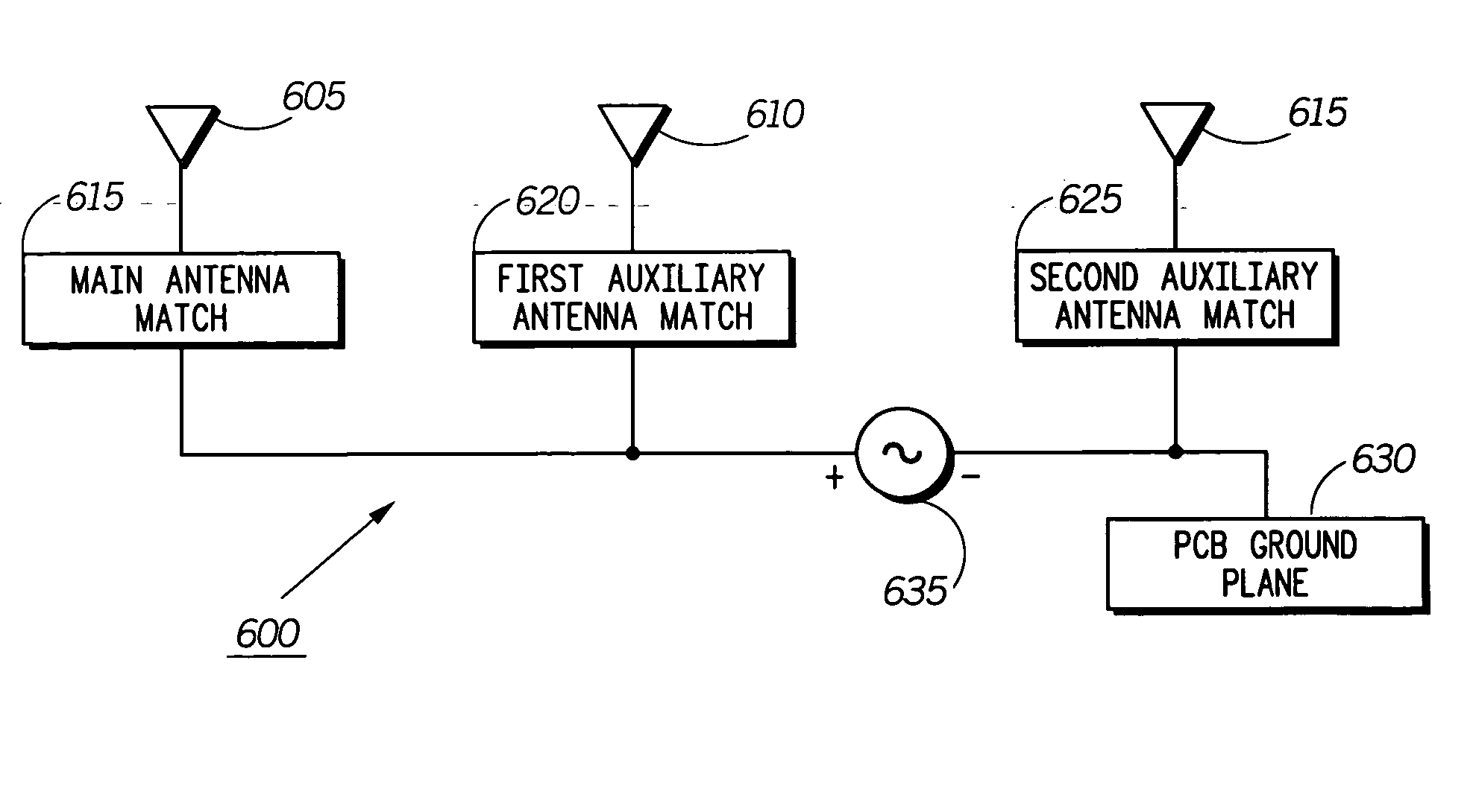
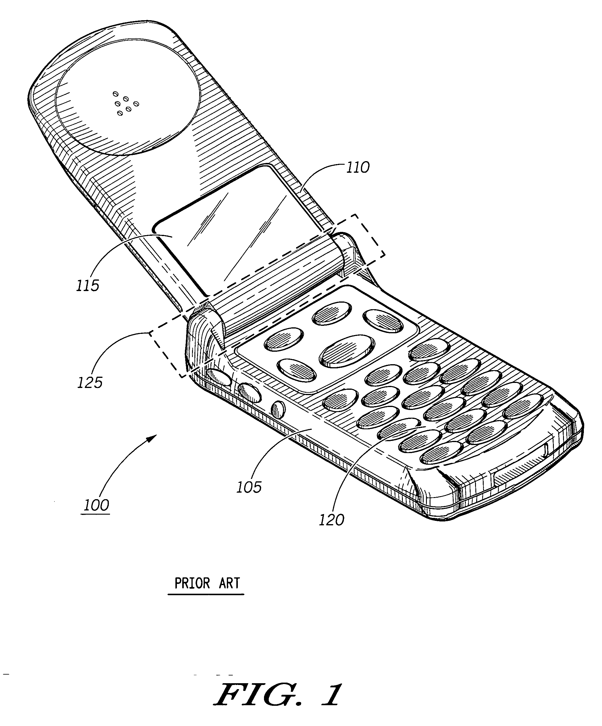
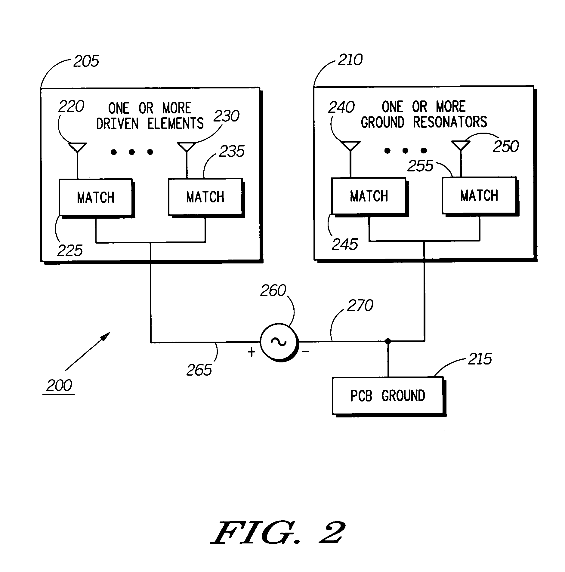
An antenna system (200,400,500,600) for use within a communication device (100) is disclosed. The communication device (100) including a signal source (260,425,635), a main housing (105) and a movable flip housing (110) moveably coupled to the main housing (105) through a hinge assembly (125). The hinge assembly (125) being comprised of a hinge shaft, a first knuckle (805) coupled to one side of the hinge shaft, and a second knuckle (810) coupled to an opposing side of the hinge shaft. The antenna system (200,400,500,600) includes at least one of the knuckles of the hinge assembly (125).

Description

BACKGROUND OF THE INVENTION [0001] 1. Field of the Invention [0002] The present invention is related to a communication device, and more particularly to an antenna system for a communication device. [0003] 2. Description of the Related Art [0004] Communication devices, such as radiotelephones, are being driven by the marketplace and technology towards smaller, more compact sizes and form factors. Consumer and user demand has continued to push a dramatic reduction in the size of such communication devices. The reduction in size provides additional challenges to the device designers to achieve adequate antenna electrical performance. [0005] To create a more compact package, many communication devices in use today have incorporated as part of the overall communication device a flip assembly housing (also known as a clamshell assembly). A flip assembly housing typically consists of two or more housing portions that can each contain one or more printed circuit boards (PCBs) with electron...

Claims


Application Information

Patent Timeline
IPC IPC(8): H04B1/38H01Q1/08H01Q1/12H01Q1/24H01Q21/28H04B1/40
CPCH01Q1/084H01Q21/28H01Q1/243H01Q1/1207H04B1/38H04B1/40
Inventor ASRANI, VIJAY L.MORNINGSTAR, PAUL
Owner GOOGLE TECH HLDG LLC
Why Eureka
Try Eureka