
Liquid crystal display device

a display device and liquid crystal technology, applied in the direction of optics, instruments, optical light guides, etc., can solve the problems of affecting display quality, crimps, damage to optical sheets, etc., and achieve the effect of improving assembly efficiency, preventing distortion or crimps on optical sheets

Active Publication Date: 2005-05-12
JAPAN DISPLAY WEST
View PDF12 Cites 16 Cited by
  • Summary
  • Abstract
  • Description
  • Claims
  • Application Information

AI Technical Summary

Benefits of technology

[0012] The present invention has been created to solve the above-described problems of the prior art, and it is the object of the invention to provide a thinner liquid crystal display device with a larger display screen by improving the alignment and the fixing of the optical sheet.
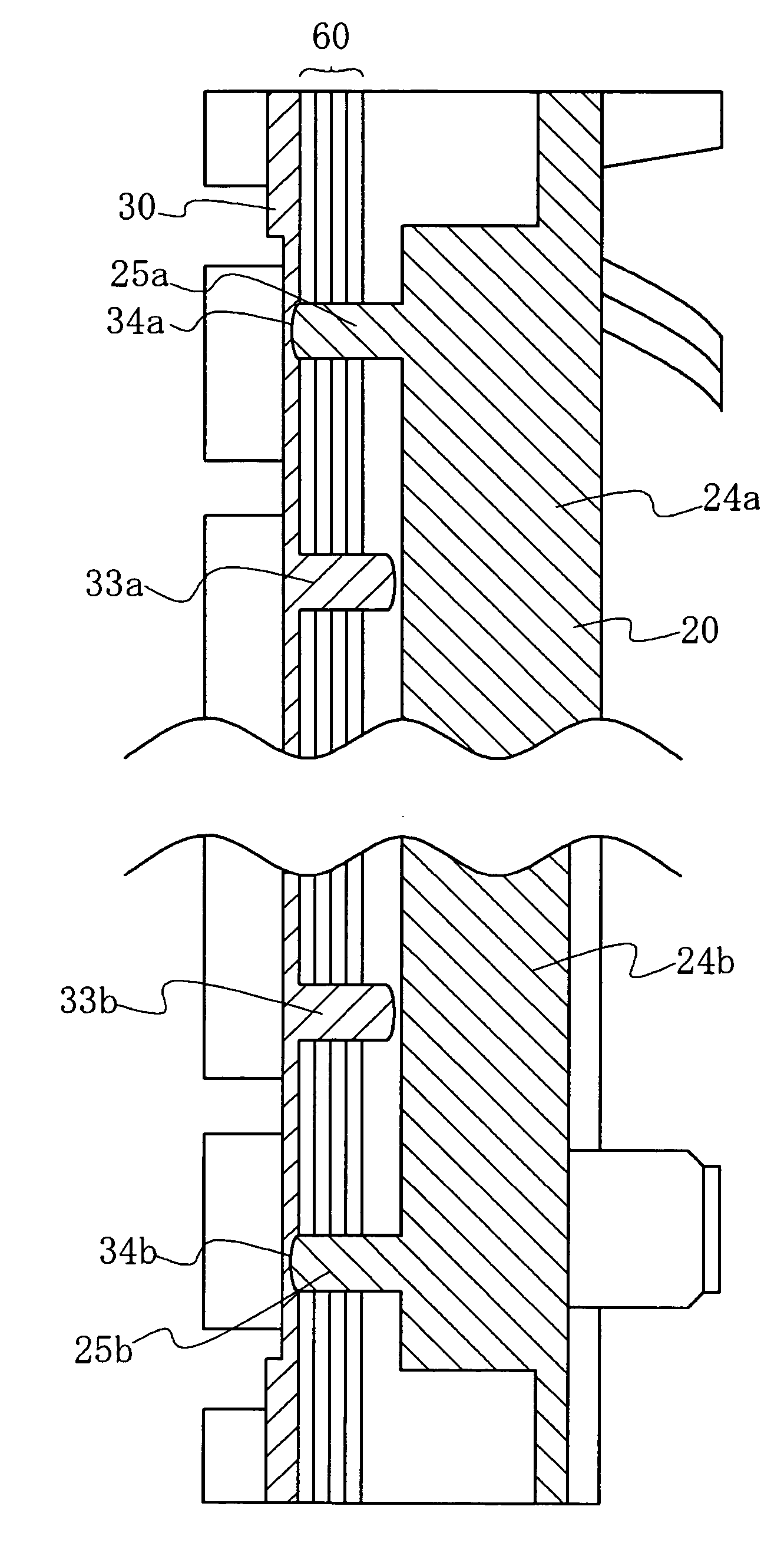
[0017] The liquid crystal display device according to the present invention constituted in the manner described above exhibits the following superior effects. Specifically, the optical sheet(s) are aligned and fixed by the first and second small protrusions provided in the main frame and the sub-frame from vertical directions without making the first small protrusions penetrate the sub-frame. In this way, the peripheral edge of the liquid crystal panel can be extended more closely to the peripheral side edge of the sub-frame even if the width of the latter is made narrower, so that the display screen of the liquid crystal panel can be made larger.
[0018] Further, since the optical sheet(s) are fixed only on one side of the main frame, the optical sheet(s) can move freely when they expand or contract during use due to heat generated by the light source because one side of the optical sheet(s) remains fixed while the other end is free, and thus distortion of or crimps forming on the optical sheet(s) can be prevented. Additionally, since adhesive tape is not used, melting of the adhesive agent does not occur, and therefore display quality is not affected and ultimately, the level of efficiency of assembly work is improved.
[0019] Moreover, since the small protrusions can integrally form part of the two frames, the number of components is reduced, making assembly work more efficient.
[0020] Furthermore, according to the liquid crystal display device of the present invention, the first small protrusions do not protrude from the frame piece of the sub-frame when the sub-frame is connected and installed to the main frame. Accordingly, the optical sheet(s) are aligned and fixed by the first and second small protrusions provided on the main frame and the sub-frame from vertical directions in a stable manner, and therefore, the window of the sub-frame can be made larger and concurrently, the liquid crystal display device can be made thinner.

Problems solved by technology

However, when the liquid crystal panel is moved or forcefully struck from the outside, there have been cases where the optical sheets were damaged because they could not expand or contract freely, being firmly fixed by double-sided adhesive tape, causing crimps to occur.
Likewise, there have been cases where the display surface would become contaminated when the adhesive agent of the double-sided adhesive tape melts due to heat generated by a light source, if the adhesive quality of the double-sided adhesive tape is inferior.
Further, the liquid crystal display device was also preferably made thicker through the use of greater amounts of double-sided adhesive tape, thereby entailing higher costs.
Therefore, as the number of requisite components has increased, installation thereof into the main frame 102 is troublesome, thereby impairing work efficiency.
Further, since it is fixed firmly on both sides, crimps could occur when the optical sheet expands and contracts due to heat, thereby causing damage thereto.
As a result, the display screen of the liquid crystal panel becomes substantially smaller.

Method used


Image

  • Liquid crystal display device
  • Liquid crystal display device
  • Liquid crystal display device

Examples


Embodiment Construction

[0029] The best embodiments for carrying out the present invention will be described hereafter with reference to the accompanying drawings. However, while the embodiments explained below exemplify the technical concept of the present invention, they are not in any way intended to restrict the application of the present invention to liquid crystal display devices, since other embodiments included in the scope of the claims equally apply to other kinds of devices.

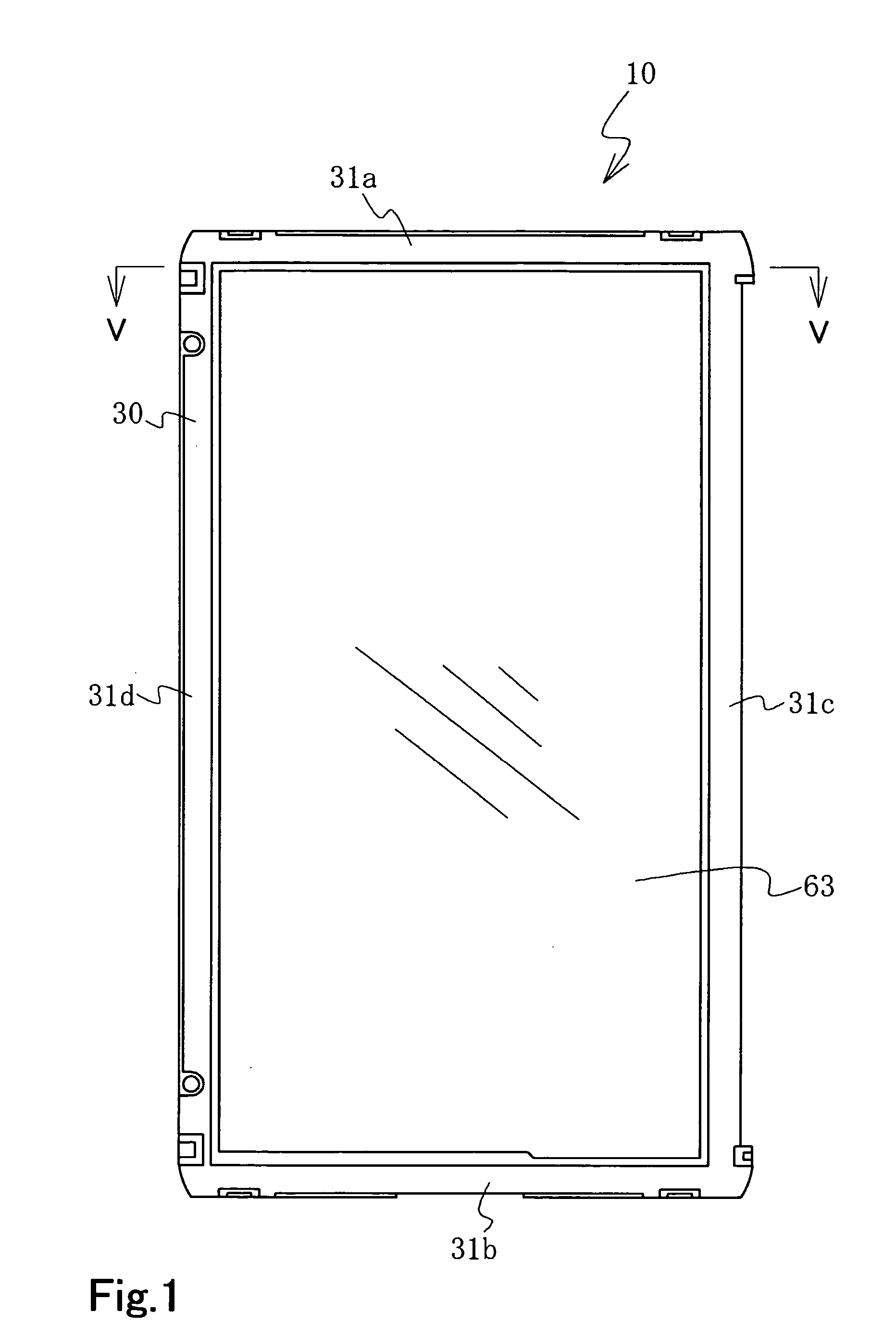
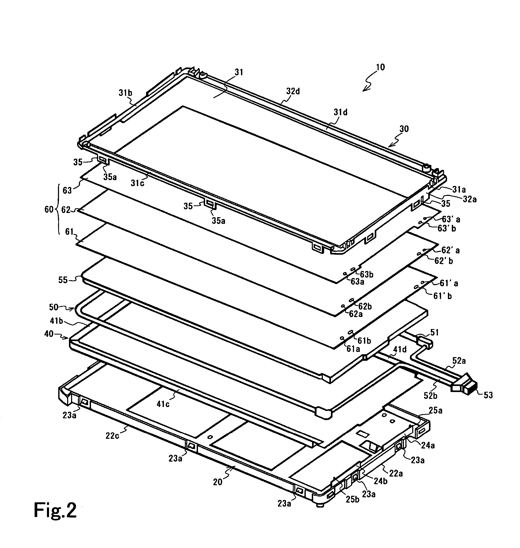
[0030] As shown in FIG. 2, a liquid crystal display device 10 is provided with a light source 50, a flat light guiding plate 55 for transmitting light from the light source 50, a reflector 40 disposed along the rear surface of the light guiding plate 55, and optical sheets 60 placed on the light guiding plate 55, in which the said components are laminated to form a body inserted between a main frame 20 and the sub-frame 30, and the laminated body is aligned and fixed by connecting and installing the sub-frame 30 to the main ...


PUM


Abstract

A liquid crystal display device includes a liquid crystal panel, at least one optical sheet substantially rectangular in shape, where first and second openings are formed on the end edges of one side of the optical sheet at a predetermined interval, a main frame in which the optical sheet(s) are placed, and a sub-frame arranged above the main frame, in which the main frame is provided with first small protrusions jutting upward corresponding to the first openings at the top surface, while the rear surface of the sub-frame is provided with second small protrusions jutting downward corresponding to the second openings, thereupon the first small protrusions are inserted into the first openings of the optical sheet(s) and the second small protrusions are inserted into the second openings to connect and install the sub-frame to the main frame, and the optical sheet(s) are then aligned and fixed. Accordingly, the optical sheets are aligned better and firmly fixed to achieve larger display screens and thinner liquid crystal display devices.

Description

TECHNICAL FIELD [0001] The present invention relates to a liquid crystal display device, more specifically to a liquid crystal display device in which the alignment and the fixing of optical sheets is improved to achieve larger display screens and thinner devices. BACKGROUND ART [0002] In conventional liquid crystal display devices, several optical sheets are generally inserted between a light guiding plate and a liquid crystal panel and usually affixed to a main frame by using double-sided adhesive tape. [0003] However, when the liquid crystal panel is moved or forcefully struck from the outside, there have been cases where the optical sheets were damaged because they could not expand or contract freely, being firmly fixed by double-sided adhesive tape, causing crimps to occur. Likewise, there have been cases where the display surface would become contaminated when the adhesive agent of the double-sided adhesive tape melts due to heat generated by a light source, if the adhesive qu...

Claims


Application Information

Patent Timeline
IPC IPC(8): G02F1/1333G02F1/13G02F1/13357
CPCG02F1/133308G02F1/133615G02B6/0088G02F2201/54G02F2001/133317G02F1/133317G02F1/1333
Inventor HAYANO, SATOSHI
Owner JAPAN DISPLAY WEST
Learn More