Portable terminal

a terminal and portability technology, applied in the field of portability terminals, can solve the problems of limiting the ability to increase the display size, and achieve the effect of large display and small siz

Inactive Publication Date: 2008-09-18
LG ELECTRONICS INC
View PDF11 Cites 52 Cited by
  • Summary
  • Abstract
  • Description
  • Claims
  • Application Information

AI Technical Summary

Benefits of technology

[0009]Accordingly, in order to solve the above-mentioned problems, an object of the present invention is to provide a portable terminal which is small in size and implements a large display by removing a sound emission hole at a front surface of a body and implementing a display screen at the entire front surface of the body.

Problems solved by technology

However, because related art portable terminal has the sound emission hole at the front surface of the first body where the display is mounted for emitting sound generated by the receiver to the exterior of the portable terminal, the sound emission hole limits the ability to increase size of the display.

Method used


Image

  • Portable terminal
  • Portable terminal
  • Portable terminal

Examples


first embodiment

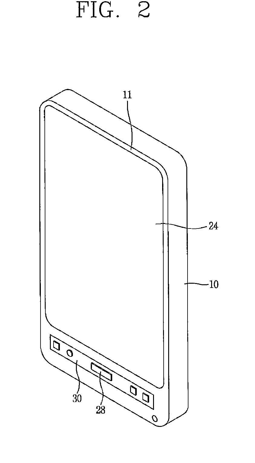
[0034]FIG. 2 is a perspective view showing a portable terminal according to the present invention, and FIG. 3 is a schematic sectional view of the portable terminal of FIG. 2.

[0035]The portable terminal according to the present invention includes a body 10, a display unit 12 located in the body 10 to display information, a touch screen 14 attached to a front surface of the display unit 12 to generate input when being touched, a battery 16 detachably located at a rear surface of the body 10 to supply power, a speaker unit 20 including a bone conduction speaker 20 located in the body 10 to transmit a sound through bone conduction, and a microphone 22 located at a lower portion of the body 10 to input a sound.

[0036]A display window 24 is located at the front surface 11 of the body 10 so as to show information displayed in the display unit 12 to the exterior. A circuitry supporting substrate (CSS), for example, a main printed circuit board 18, is located inside the body 10 to mount vari...

second embodiment

[0051]That is, the speaker unit 40 has a structure such that the transducer can transmit a sound through both bone conduction and air conduction. Different voltages can be applied to the transducer based on whether the sound is transmitted through bone conduction or through air conduction.

[0052]In addition, when the speaker unit 40 is operated as an air conduction speaker, a sound emission hole 42 may be formed at a rear surface of the body 10 to emit the sound generated by the transducer to the exterior of the body 10.

[0053]When the portable terminal according to the second embodiment is used to make a call, the speaker unit 40, functioning as a bone conduction speaker, transmits vibration generated from the transducer of the speaker unit 40 to the skull through the body 10. Accordingly, the user can hear the sound.

[0054]Further, when the portable terminal is used to listen to music such as, for example, an MP3, the speaker unit 40, functioning as the air conduction speaker, exits...

third embodiment

[0057]That is, the bone conduction speaker of the speaker unit 32 is located at the rear surface of the display unit 12, and the bone conduction transducer of the bone conduction speaker 32 is contacted with the rear surface of the display unit 12, thereby transmitting vibration generated by the bone conduction transducer to the facial bones through the display unit 12 and the body 10.

[0058]FIG. 6 is a schematic sectional view showing the portable terminal according to a fourth embodiment of the present invention. The portable terminal according to the fourth embodiment includes a first body 60 having a display unit 62 for displaying information at a front surface of the first body 60; and a second body 70 rotatably coupled to the first body 60 by a hinge-connecting portion 64. The second body includes a keypad 72 configured to generate input at a front surface of the second body 70, a CSS 74 mounted inside the second body 70, and a battery 76 detachably mounted at a rear surface o...


PUM


Abstract

A portable terminal in provided. The portable terminal includes a body having a front surface, the front surface having an upper portion and a lower portion, a display unit located in the body and visible at the front surface thereof, the display unit having a first end and a second end, and at least one of the first end being adjacent the upper portion and the second end being adjacent the lower portion, and a speaker unit located in the body, the speaker unit including a bone conduction speaker.

Description

CROSS REFERENCE TO RELATED APPLICATIONS[0001]This application claims the benefit of Korean Patent Application No. 10-2007-0026329, filed Mar. 16, 2007, and is herein incorporated by reference.BACKGROUND OF THE INVENTION[0002]1. Field of the Invention[0003]The present invention relates to a portable terminal, and more particularly to a portable terminal that is small in size but implements a large display.[0004]2. Description of Related Art[0005]FIG. 1 is a schematic sectional view showing a portable terminal according to the related art. The portable terminal according to the related art includes a first body 100 having a display 102 configured to display information and a speaker 104 configured to emit a sound to the exterior of the portable terminal. The front surface of the first body 100 is divided into a speaker mount space P for mounting the speaker 104 and a display mount space Q for mounting the display 102. A sound emission hole 106 is formed at the front surface of the fir...

Claims


Application Information

Patent Timeline
Patent Type & Authority Applications(United States)
IPC IPC(8): H04M1/00
CPCG06F1/1616G06F1/1624H04M1/03G06F1/1656G06F1/1626H04B1/38
Inventor JOO, WON SEOKAHN, KWANG HYUN
Owner LG ELECTRONICS INC
Why Eureka
Try Eureka