Write-head having recessed magnetic material in gap region

a write-head and gap-area technology, applied in the field of magnetic write-heads, can solve the problems of affecting the data integrity of the system, unintended erasure of adjacent tracks on the disk, etc., and achieve the effect of limiting the width of material and reducing the magnetic influence of adjacent tracks

Inactive Publication Date: 2005-05-12
HEADWAY TECH INC
View PDF19 Cites 10 Cited by
  • Summary
  • Abstract
  • Description
  • Claims
  • Application Information

AI Technical Summary

Benefits of technology

[0012] These objects have been achieved by limiting the width of material in the ABS plane to what it is at the write gap. The part of the lower pole that is wider than this is recessed away from the ABS, thereby greatly reducing its magnetic influence on adjacent tracks. Four different embodiments of write heads that incorporate this notion are described together with a description of a general process for their manufacture.

Problems solved by technology

One consequence of this, the standard structure in use today, is the unintended erasure of adjacent tracks on the disk as narrower tracks and higher track densities are developed.
This may lead to unintended writing on an adjacent track and may therefore affect the data integrity of the system.

Method used


Image

  • Write-head having recessed magnetic material in gap region
  • Write-head having recessed magnetic material in gap region
  • Write-head having recessed magnetic material in gap region

Examples


1st embodiment

1st Embodiment

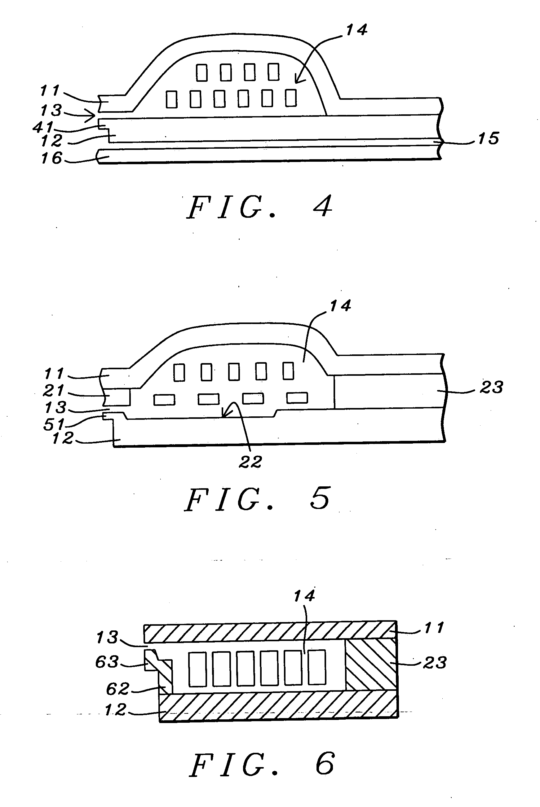
[0024] Referring now to FIG. 4, we show there a structure that is similar to the one shown in FIG. 1, but modified in accordance with the teachings of the present invention. As before, upper pole 11 and lower pole 12 enclose, between them, field coil 14. The key novel feature is ledge 41 of magnetic (high permeability) material that extends outwards away from the main body of lower pole 12. The outer edge of ledge 41 has the same width as, and is in alignment with, the outer edge of top pole 11 so that write gap 13 lies between them and said widths define the track width TW. As a result, most of bottom pole 12 is set back some distance from the ABS and so has relatively little magnetic interaction with the disk surface. FIG. 7 is an isometric view that illustrates the spatial relationships between top pole 11 and bottom poles 41 and 12.

[0025] For purposes of simplification, FIG. 4 has been drawn as though ledge 41 is a cantilever. In actuality, a layer of insulation i...

2nd embodiment

2nd Embodiment

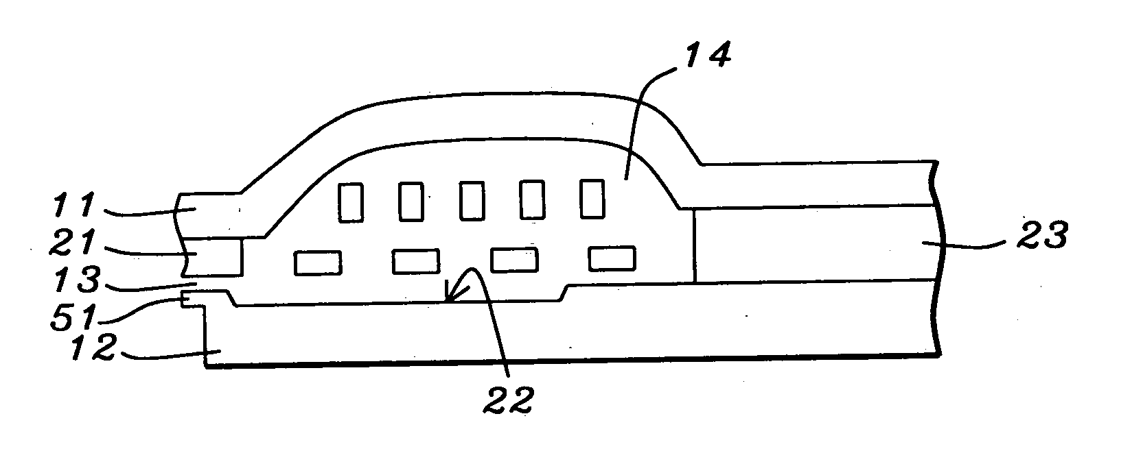
[0026]FIG. 5 shows a structure similar that seen in FIG. 2. As before, there is a general similarity to the first embodiment illustrated in FIG. 4 with the addition of stitched secondary top pole 21 and shallow trench 22. The key departure is the addition to the structure of ledge 51, which analogous to ledge 41 of the first embodiment, and serves the same purpose. FIG. 7 is an isometric view that illustrates the spatial relationships between top pole 21 and bottom poles 51 and 12 while FIG. 13 is a plan view of this structure.

3rd embodiment

3rd Embodiment

[0027] This variation of the basic structure is sometimes preferred because certain parts, such as pole 11, are easier to manufacture. By going to a somewhat thicker inter-pole connector 23 and using a single turn for field coil 23, top pole 11 can be flat rather than humped, as in the previous two embodiments. The bottom pole in this case is composed of two layers, 62 and 12, which, in prior art versions of this variant (not shown), would extend from bottom pole 12 all the way to write gap 13.

[0028] As seen in FIG. 6, in the structure of the present invention the secondary bottom pole is in two parts 62 and 63. Part 62 extends upwards from bottom pole 12 but not all the way to write gap 13. This leaves room for second part 63 which, in addition to extending the rest of the way up to the write gap, also extends laterally away from part 62 so as to be aligned with the ABS end of top pole 11. As a result, the lower part of the secondary bottom pole and all of the main b...


PUM

PropertyMeasurementUnit
track widthaaaaaaaaaa
thicknessaaaaaaaaaa

Abstract

As track densities increase, it becomes increasingly important, while writing in a given track, not to inadvertently write data in adjoining tracks. This problem has been overcome by limiting the width of material in the ABS plane to what it is at the write gap. The part of the lower pole that is wider than this is recessed back away from the ABS, thereby greatly reducing its magnetic influence on adjacent tracks. Four different embodiments of write heads that incorporate this notion are described together with a description of a general process for their manufacture.

Description

FIELD OF THE INVENTION [0001] The invention relates to the general field of magnetic write heads with particular reference to eliminating neighboring track erasure. BACKGROUND OF THE INVENTION [0002] A typical write head structure for a magnetic disk system is schematically illustrated in FIG. 1. Its principal parts are lower pole 12 and upper pole 11 (commonly referred to as P1 and P2, respectively. These are magnetically connected at one end and separated by a small non-magnetic layer 13 (the write gap) at the other end. The track width will be defined by the P2 width at the gap. P1 may be notched through a self aligned process, known as partial pole trim (PPT), to better define the written transitions. Coil 14 is located in the space enclosed by P1 and P2 and is the source of the magnetic field that is focused by the two pole pieces. All seen in the figure is a magnetic shield layer 16 which is electrically isolated from the lower pole by dielectric layer 15. [0003]FIG. 2 shows a...

Claims


Application Information

Patent Timeline
Patent Type & Authority Applications(United States)
IPC IPC(8): G11B5/147G11B5/265
CPCG11B5/2657Y10T29/49021Y10T29/49043Y10T29/49046Y10T29/49048Y10T29/49044Y10T29/49052
Inventor DOVEK, MORISGARFUNKEL, GLENWANG, PO KANG
Owner HEADWAY TECH INC
Why Eureka
Try Eureka