Coil component

a technology of coils and components, applied in the direction of transformers/inductance coils/windings/connections, transformers/inductance coils/windings/connections, etc., can solve the problems of difficult to ensure high transmission efficiency, reduce loss caused by magnetic field influence, and suppress the effect of transmission efficiency reduction

Active Publication Date: 2020-08-27
TDK CORPARATION
View PDF9 Cites 1 Cited by
  • Summary
  • Abstract
  • Description
  • Claims
  • Application Information

AI Technical Summary

Benefits of technology

[0015]The coil component according to the present invention may further have a fifth coil pattern wound in a planar spiral shape, at least one turn constituting the fifth coil pattern may be divided into a plurality of lines by a spiral slit, and when a seventh virtual line extending in the first direction with a third reference point positioned in an inner diameter area of the fifth coil pattern as a starting point and an eighth virtual line extending in the third direction with the third reference point as a starting point are defined, a space width between the plurality of lines may be larger along the eighth virtual line than along the seventh virtual line, and the first and fifth coil patterns may overlap each other such that the seventh virtual line passes the inner diameter area of the first coil pattern in a plan view. Thus, when the coil component according to the present invention is used as a power transmitting coil of a wireless power transmission system, it is possible to suppress a reduction in transmission efficiency even when a power receiving coil is positioned between the first and third coil patterns or between the first and fifth coil patterns in a plan view.
[0016]In this case, the third and fifth coil patterns may be formed on the same insulating substrate. This allows the relative position between the third and fifth coil patterns to be fixed.
[0017]In the present invention, the first coil pattern may have an innermost turn positioned on the innermost peripheral side, an outermost turn positioned on the outermost peripheral side, and an intermediate turn whose turn number counting from the innermost or outermost turn is at the center of the total number of turns, the innermost turn, outermost turn, and intermediate turn may each be divided by a spiral slit into a plurality of lines, and the line width of each of the plurality of lines constituting each of the inner and outermost turns may be smaller than the line width of each of the plurality of lines constituting the intermediate turn. Since the line width of the innermost turn and that of the outermost turn are small, a loss caused due to the influence of a magnetic field can be reduced.
[0018]In this case, the line width of each of the plurality of lines constituting the innermost turn may be smaller than the line width of each of the plurality of lines constituting the outermost turn, and this makes it possible to reduce the loss at the innermost turn to be exposed to a strongest magnetic field.
[0019]The coil component according to the present invention may further have a sixth coil pattern wound in a planar spiral shape and a magnetic sheet, the first and sixth coil patterns may be disposed so as to overlap the magnetic sheet in a plan view, the first and sixth coil patterns may be connected in parallel, the first coil pattern is disposed closer to the magnetic sheet than the sixth coil pattern, a line length of the sixth coil pattern may be larger than that of the first coil pattern. Since a difference is provided between the line lengths of the first and sixth coil patterns, impedance of each coil pattern can be finely adjusted. This allows a difference in impedance between the first and sixth coil patterns can be reduced, so that the impedance difference in the entire coil component can be reduced. As a result, a loss caused due to the impedance difference can be reduced.
[0020]As described above, according to the present invention, there can be provided a coil component having a high degree of freedom of design. Thus, when the coil component of the present invention is applied to a power transmitting coil of a wireless power transmission system, high transmission efficiency corresponding to the specification or shape of an application product can be ensured.

Problems solved by technology

Thus, it is difficult to ensure high transmission efficiency corresponding to the specification or shape of an application product only by simply using a plurality of power transmitting coils as in the wireless power transmission system described in JP 2018-102124A and Japanese Patent No. 5,686,769.

Method used


Image

  • Coil component
  • Coil component
  • Coil component

Examples


Embodiment Construction

[0039]Preferred embodiments of the present invention will be explained below in detail with reference to the accompanying drawings.

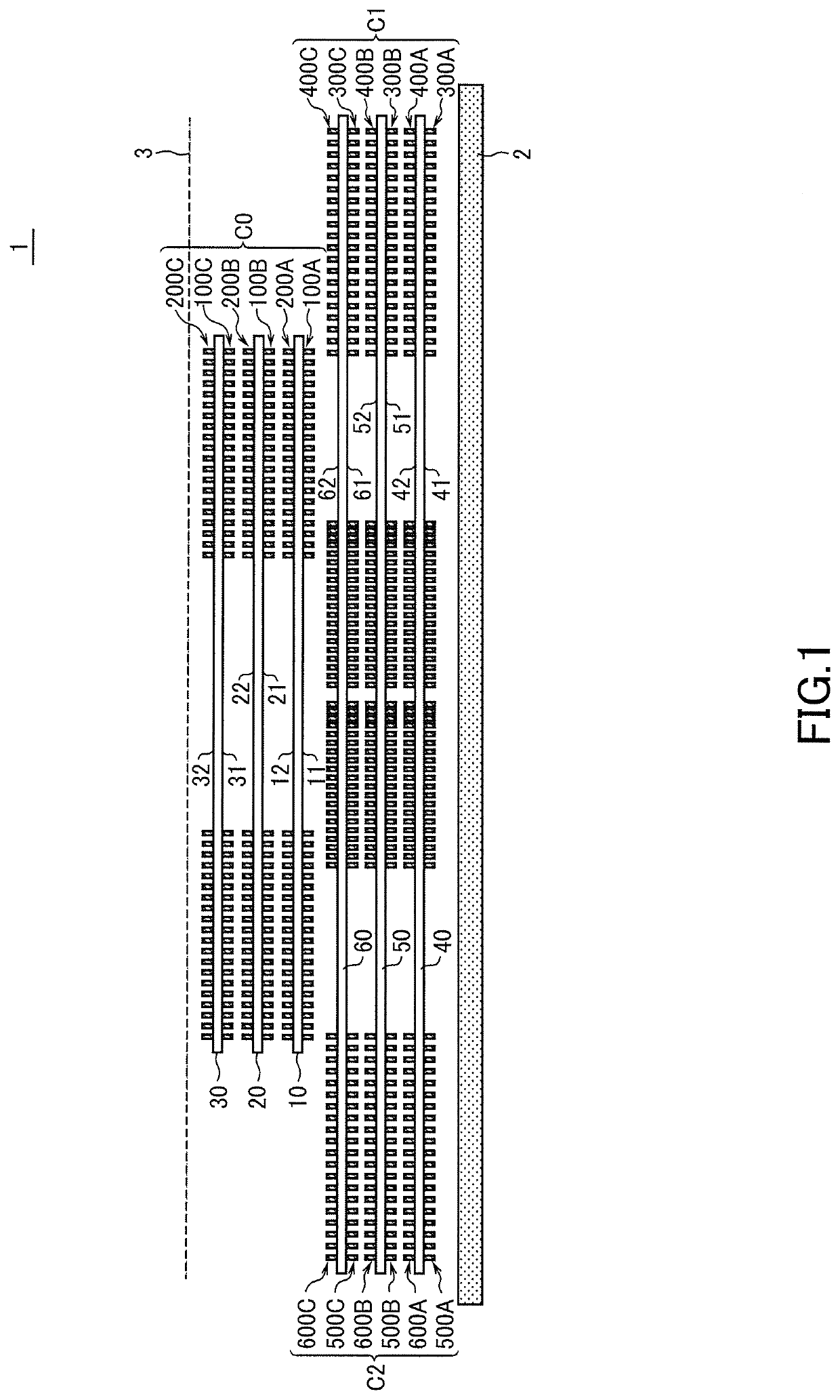
[0040]FIG. 1 is a schematic cross-sectional view for explaining the configuration of a coil component 1 according to a preferred embodiment of the present invention.

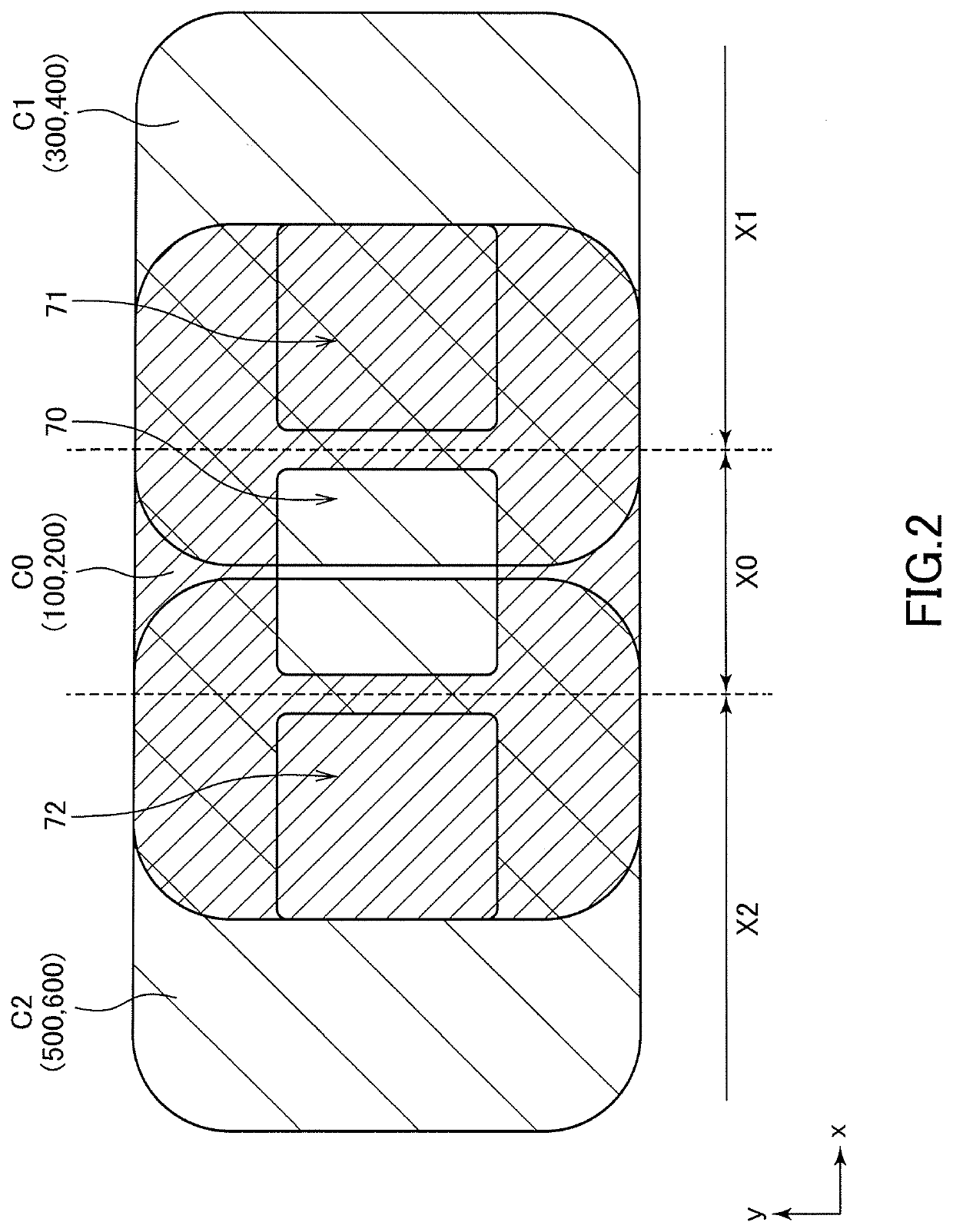
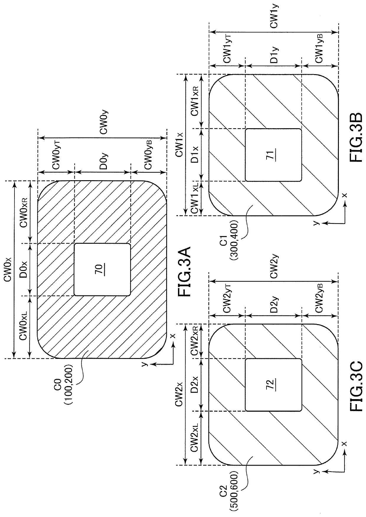
[0041]As illustrated in FIG. 1, the coil component 1 according to the present embodiment includes a magnetic sheet 2, a center coil C0, a first side coil C1, and a second side coil C2 each of which is disposed so as to overlap the magnetic sheet 2.

[0042]The magnetic sheet 2 is a sheet member made of as high permeability material such as ferrite, permalloy, or a composite magnetic material and functions as a magnetic path for magnetic flux that interlinks with the center coil C0 and side coils C1, C2. Although not particularly limited, the coil component 1 according to the present embodiment can be used as a power transmitting coil of a wireless power transmission system. In this case, a power...


PUM

PropertyMeasurementUnit
thicknessaaaaaaaaaa
space widthaaaaaaaaaa
inner diameteraaaaaaaaaa

Abstract

Disclosed herein is a coil component that includes a first coil pattern wound in a planar spiral shape . At least one turn constituting the first coil pattern is divided into a plurality of lines by a spiral slit, and a space width between the plurality of lines differs depending on a planar position.

Description

BACKGROUND OF THE INVENTIONField of the Invention[0001]The present invention relates to a coil component and, more particularly, to a coil component suitable for use in wireless power transmission systems.Description of Related Art[0002]In recent years, wireless power transmission systems that feed electric power from a power transmitting side to a power receiving side by wireless are put in practical use. The wireless power transmission systems are expected to be applied to various products including transport equipment such as electric trains or electric cars, household appliances, electronic equipment, wireless communication devices, toys, and industrial equipment. For example, JP 2018-102124A and Japanese Patent No. 5,686,769 propose a wireless power transmission system provided with a plurality of power transmitting coils on the power transmitting side.[0003]Although not related to the wireless power transmission systems, JP 1996-203739A and JP 2003-197438A disclose a coil comp...

Claims


Application Information

Patent Timeline
Patent Type & Authority Applications(United States)
IPC IPC(8): H02J50/10H04B5/00H01F5/04H01F27/28
CPCH01F27/2828H01F5/04H04B5/0081H02J50/10H04B5/0037H01F38/14H01F27/2871H02J50/12H01F27/2804H01F27/255H01F5/003H01F2027/2809H02J50/402
Inventor CHIYO, NORITAKATOMONARI, TOSHIOKANEKO, SHIGERUHIRATA, SHIGENORIWATANABE, AKIHITOASOU, HIROHUMIHAYAMA, JUNPEIOHTSUKA, SHIGEKIOHISHI, TAKAHIROIMAI, TAKAAKIMORIKI, TOMOHIROMARUYAMA, TAKAKAZU
Owner TDK CORPARATION
Why Eureka
Try Eureka