Electric current detector

a technology of electric current detector and detector, applied in the direction of magnetic measurement, instruments, nanomagnetism, etc., can solve the problems of decreasing detection accuracy and growing the size of conventional electric current detector, and achieve the effect of sufficient detection sensitivity and improved detection accuracy

Inactive Publication Date: 2008-04-24
KK TOKAI RIKA DENKI SEISAKUSHO
View PDF5 Cites 28 Cited by
  • Summary
  • Abstract
  • Description
  • Claims
  • Application Information

AI Technical Summary

Benefits of technology

[0070] According to the present embodiment, the following advantageous effects can be attained.
[0071] (1) Since the magnetic detection element 22 is disposed between the parallel portions 41A and 41B of the concave portion 3 formed in the bus bar 4B, a magnetic flux is given to the magnetic detection element 22 from the parallel portions 41A and 41B, respectively, upon energization, so that sufficient detection sensitivity can be obtained even in a coreless structure. Thus, downsizing due to the coreless structure becomes possible.
[0072] (2) Since the magnetic detection element 22 is shielded by the shield member 5 and the concave portion 3 of the bus bar 4B from external magnetic field, the influence of magnetic fluxes from the adjacent bus bars 4A and 4C can be reduced, whereby detection accuracy can be improved.
[0073] In the following, examples of the present invention will be described.

Problems solved by technology

However, a conventional electric current detector grows in size, because cores occupying a space are necessary.
Furthermore, when a plurality of bus bars is disposed adjacently, the magnetic field due to the adjacent bus bars is applied to a magnetosensitive element, so that a cause for decrease in detection accuracy arises.

Method used


Image

  • Electric current detector
  • Electric current detector
  • Electric current detector

Examples


example 1

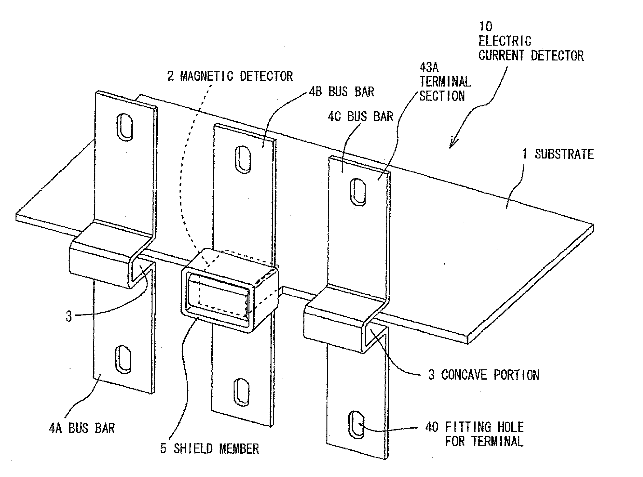
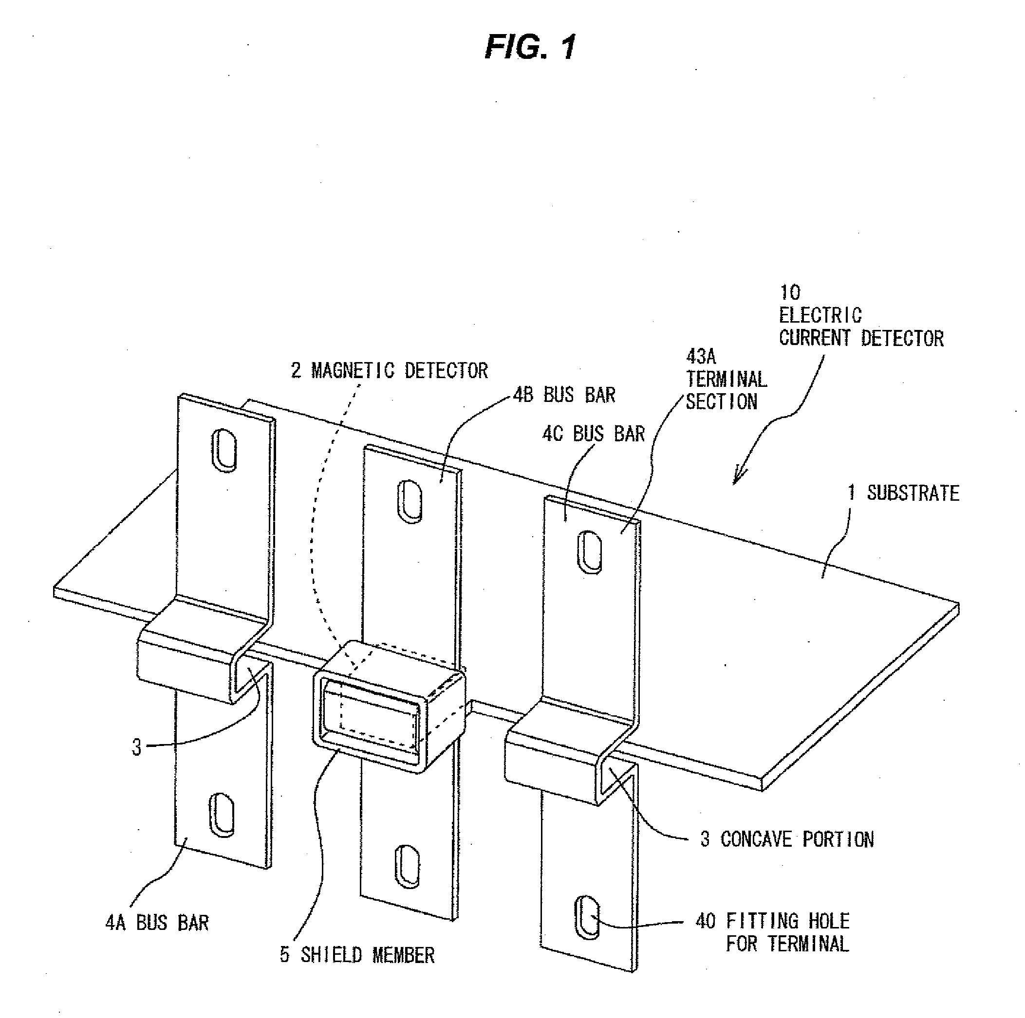
[0074]FIG. 7 is a characteristic graphical representation wherein a relationship between the electric current of a bus bar and the magnetic flux given to a magnetic detector is shown. The magnetic flux density in the case when an electric current of 0 to 350 A is applied to the bus bar 4B in the magnetic detector 2 having the construction shown in FIGS. 1 and 2 is measured (the ordinate on the left side of FIG. 7).

[0075] As a result, magnetic flux density in response to the direction of electric current can be measured in a linear characteristic region on the border of about 30 (mT) as shown in FIG. 7. Namely, the direction of electric current can be detected.

[0076] On one hand, a degree of influence (%) due to the bus bars 4A and 4C adjacent to the bus bar 4B is also measured. The measurement is conducted in such that an electric current of from 0 to 350 A is applied step-by-step to the bus bar 4B, while an electric current of 350 A (fixed) is applied to the bus bars 4A and 4C, r...

example 2

[0078]FIG. 8 is a characteristic graphical representation showing a relationship between the electric current and the magnetic flux of the magnetic detector 2 wherein the shield member 5 is provided; and FIG. 9 is Comparative Example of a characteristic graphical representation showing a relationship between the electric current and the magnetic flux of the magnetic detector 2 wherein the shield member 5 is not provided.

[0079] In Example 2 shown in FIG. 8, a magnetic flux density in the case where the electric current flowing through the bus bar 4B is 300 A is 22 mT, while in Comparative Example of FIG. 9, a magnetic flux density in the case where the electric current flowing through the bus bar 4B is 300 A is 14.5 mT. Accordingly, the magnetic flux density in Example 2 is about 1.52 times higher than that of Comparative Example. This means that the magnetic flux density increases, in other words, sensitivity increases as a result of providing the shield member 5. In addition, it b...

example 3

[0080]FIGS. 10A and 10B are perspective views each showing another shape of the bus bar as an electric conductor wherein a bus bar 4D has a first portion 41C and a second portion 41D being different circular arc profile from one another surrounding the concave portion 3 of the bus bar 4D. The first magnetic flux generated due to the electric current flowing through the first portion 41C is added to the second magnetic flux generated due to the electric current flowing through the second portion 41D in the region of the concave portion 3. Furthermore, the bus bar 4E having the shape shown inFIG. 10B is the same as that of the bus bar 4D mentioned above wherein the bus bar 4E has a first portion 41E and a second portion 41F being flat different portions from one another surrounding the concave portion 3 of the bus bar 4E. The first magnetic flux generated due to the electric current flowing through the first portion 41E is added to the second magnetic flux generated due to the electri...


PUM


Abstract

An electric current detector has a bus bar with a current direction changing section for changing a direction of electric current through the bus bar, and a magnetic detector disposed in the current direction changing section of the bus bar. The current direction changing section of the bus bar has a pair of parallel portions at which the bus bar is orthogonally deformed, and a connection portion at which the pair of parallel portions are connected, and the magnetic detector is disposed between the pair of parallel portions. The magnetic detector has a magnetic detection element disposed on a substrate, and a yoke surrounding the substrate and allowing the magnetic detection element to be placed between both ends thereof.

Description

[0001] The present application is based on Japanese patent application Nos. 2006-254282 and 2007-040750, the entire contents of which are incorporated herein by reference. BACKGROUND OF THE INVENTION [0002] 1. Field of the Invention [0003] The present invention relates to an electric current detector for detecting the magnitude of the electric current flowing through an electric conductor from the magnetic field thereof. [0004] 2. Description of the Related Art [0005] Heretofore, an electric current detector which can measure the electric current flowing through an electric conductor such as an electric wire and a bus bar has been used without inserting an ammeter or a resistor for detecting electric current as voltage on the way to the electric conductor such as the electric wire and the bus bar. [0006] For example, such an electric current detector wherein a ferromagnetic core having gaps so as to surround a bus bar is allowed to intervene, and magnetosensitive elements are dispos...

Claims


Application Information

Patent Timeline
Patent Type & Authority Applications(United States)
IPC IPC(8): G01R33/06G01R33/07G01R33/09
CPCB82Y25/00G01R15/207G01R33/06G01R33/07G01R33/093
Inventor MURAKI, HITOSHITANAKA, KENJI
Owner KK TOKAI RIKA DENKI SEISAKUSHO
Why Eureka
Try Eureka