Gas sensor

A gas sensor and sensor element technology, which is applied to instruments, scientific instruments, measuring devices, etc., can solve the problems of increasing the stability time and reducing the performance of the gas sensor, and achieve the effect of preventing condensation

Inactive Publication Date: 2006-04-05
TDK CORPARATION
View PDF1 Cites 2 Cited by
  • Summary
  • Abstract
  • Description
  • Claims
  • Application Information

AI Technical Summary

Problems solved by technology

In general, although the gas sensor can heat the gas detection part to a high temperature of several hundred degrees and make it work, but when the heating is stopped and the temperature of the gas sensor is cooled, condensation is prone to occur. After increasing the problem until the time to stabilize

Method used


Image

  • Gas sensor
  • Gas sensor
  • Gas sensor

Examples


Embodiment 1

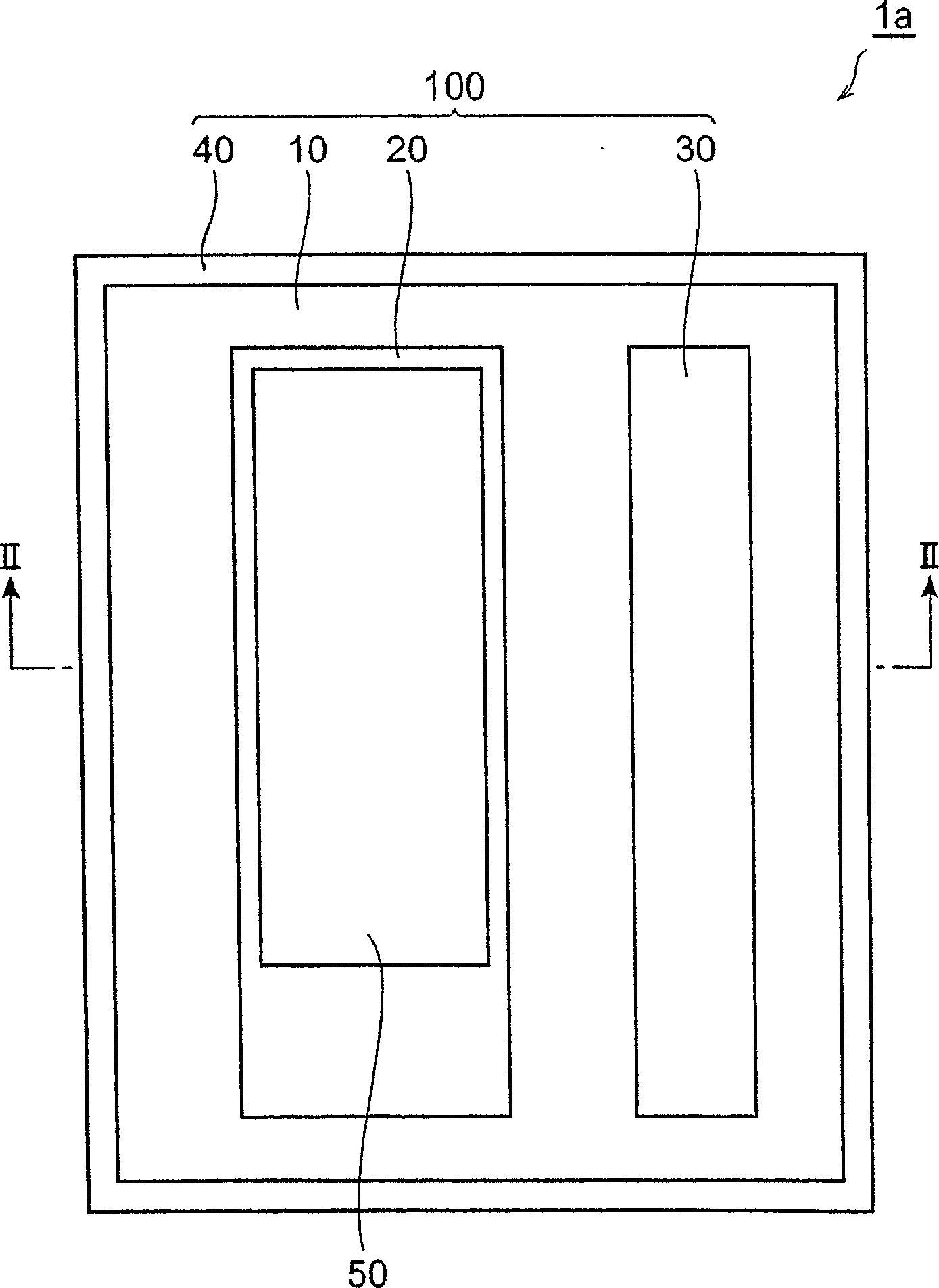
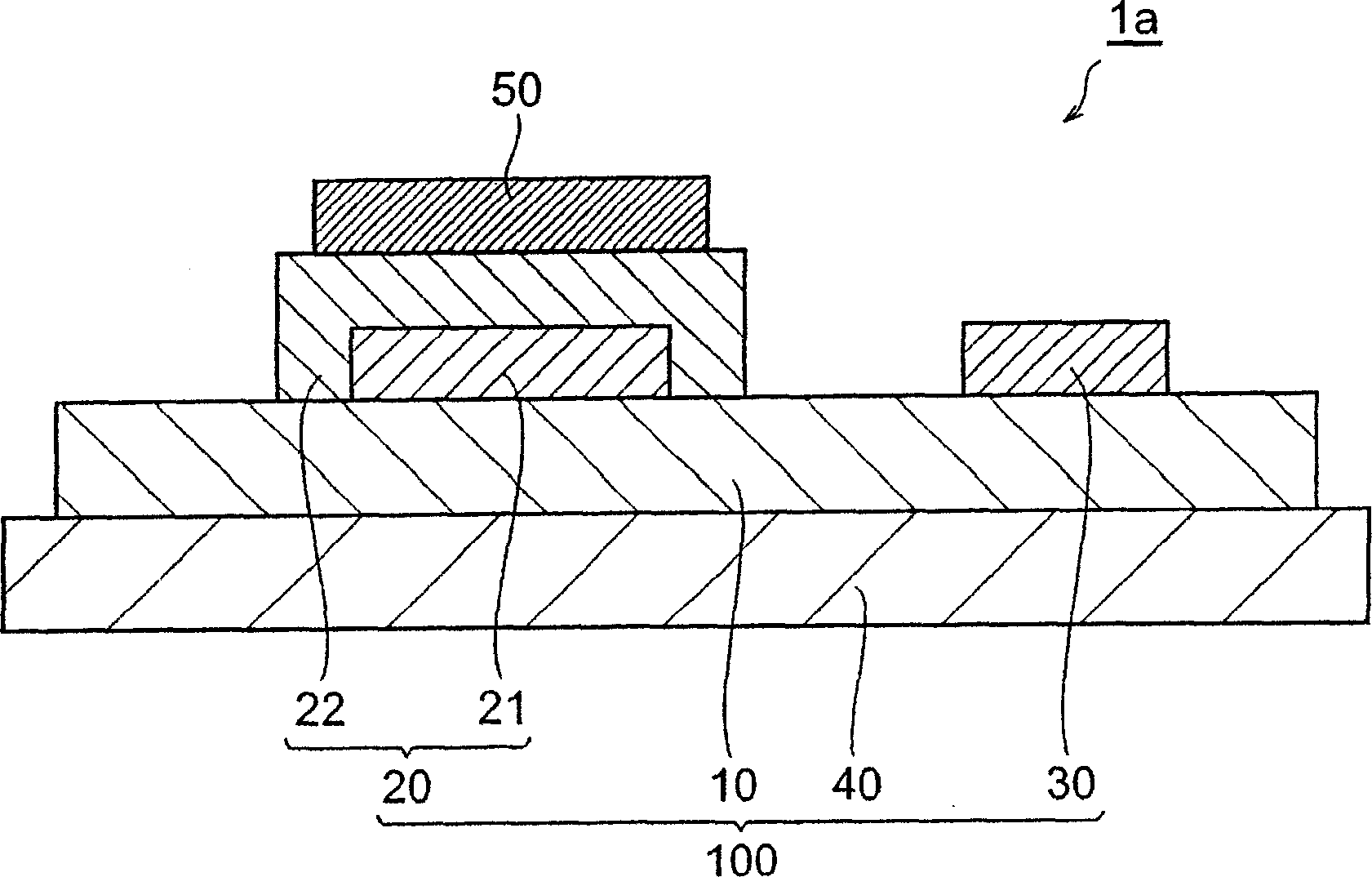
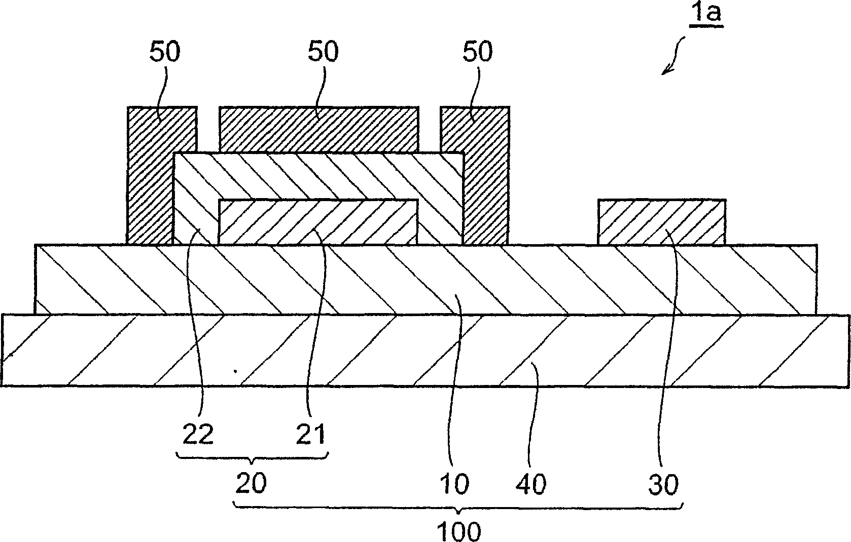
[0052] As follows, the production has the same figure 1 with figure 2 A carbon dioxide gas sensor of the same configuration as the gas sensor 1a shown in . First, a 0.5 mm thick NASICON substrate having a rectangular main surface (4 mm×4 mm) was prepared as a solid electrolyte substrate, and a 0.1 μm thick metal layer made of Au and a counter electrode were formed on the NASICON substrate by sputtering. Then, a gas detection part with a thickness of 20 μm was formed using a mixture of a compound salt of barium carbonate and lithium carbonate and indium oxide as a gas detection material covering only the metal layer of the detection electrode by a coating method. A Pt thin film was also formed as a heating portion on the surface of the NASICON substrate opposite to the gas detection portion by sputtering to obtain a gas sensor element portion.

[0053] Next, the upper surface of the gas detection part of the detection electrode was covered by coating method to form a moistur...


PUM

PropertyMeasurementUnit
thicknessaaaaaaaaaa
thicknessaaaaaaaaaa
thicknessaaaaaaaaaa

Abstract

The invention relates to a sensor element provided with gas detection in a chemical way and a gas sensor of a water removal part, which is arranged by connecting with the sensor element and is used for the water removal.

Description

technical field [0001] The present invention relates to a gas sensor including a sensor element unit that chemically detects gas. Background technique [0002] As a gas sensor that chemically detects a specific gas in the environment, a solid electrolyte type gas sensor, a semiconductor type gas sensor, and the like are known. A solid electrolyte gas sensor has, for example, a sensor element unit in which a detection electrode and a counter electrode having a gas detection unit are provided on a solid electrolyte substrate formed of a solid electrolyte, and is based on detection before and after contact between the gas detection unit and the gas to be detected. The change of the electromotive force between the poles and the poles, and the critical current generated by the contact with the gas to be detected are detected. On the other hand, a semiconductor-type gas sensor has, for example, a sensor element unit including a gas detection unit made of a metal oxide semiconduct...

Claims


Application Information

Patent Timeline
Patent Type & Authority Applications(China)
IPC IPC(8): G01N27/26G01N27/407G01N27/12
CPCG01N27/4071G01N27/4075
Inventor 小野志津子伊藤祐义
Owner TDK CORPARATION
Why Eureka
Try Eureka